Profiles and steel structures
C-sections around doors and windows: planning the cladding support
In brief
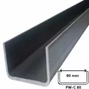
An opening in the hall wall interrupts the regular cladding layout. Support for the panels, space for flashings and suitable fixing for the gate or window must be provided. Channels can form part of such a solution, but each of these functions requires clarification. Cold-formed profiles do not become a universal surround simply by virtue of their C shape. A good detail combines the requirements of the structure, the cladding and the installed equipment. The gate dimension in an offer does not always describe the same thing as the dimension between structural members. Information is needed on the clear passage, the method of fixing and the installation space. Flashings and the panel layout must also be taken into account. The arrangement of channels should follow from the agreed dimensions. Otherwise each trade may prepare components for a different opening.
The actual opening dimension is established first
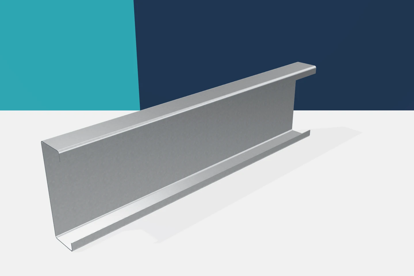
Before production, it is worth checking reference levels and planes. It matters from which side the width and height are measured. Galvanised profiles with pre-drilled holes allow efficient installation but require precise input data. An error in a few descriptions can mean reworking an entire batch of surrounds. The drawing should therefore be shared by all contractors involved.
The panel support need not carry the weight of the gate
The element used to fix the edge of the insulated panel has a specific task. A gate may introduce other loads related to its weight and mode of operation. These should not automatically be transferred to the same lightweight C-section. The equipment supplier’s requirements and the structural design must be checked. This also applies to tracks, drives and additional brackets.
The division of functions should be clear on the drawing. Sometimes cold-formed profiles form the substructure for the cladding, while a separate element carries the equipment. At other times, a proven section combines both functions. Both approaches can be correct. The problem arises when no one has assigned the load to a specific support and the contractor decides this only on site.
The orientation of the channel affects access and bearing
The open side of the C-profile can make installation easier or more difficult. Access to the screws, the bearing surface for the panel and space for the flashing must be considered. The folded stiffening edges should not conflict with the fixing. If a conflict occurs, the detail must be changed. Cutting away the return solely to insert a nut interferes with the profile geometry.
It is also worth checking whether the flange width is sufficient for the intended fasteners. The panel edge and the gate element may require separate fixing zones. The C-section should not be inadvertently overloaded with multiple functions. Z-sections, sigma or omega profiles may be present nearby, but each element must have a defined purpose.
Connections to the main structure require a detail
The surround transfers forces to the adjacent posts or rails. The connection point should be described as precisely as the profile itself. Intermediate plates, holes, screws and edge distances matter. If a sliding connection or allowance for movement is specified, its function must be preserved. Accidental blocking with an additional screw can change the operating conditions.
Do not assume that a greater number of fasteners always improves the connection. Additional holes weaken the sheet section and can alter the transfer of forces. Galvanised profiles require connections matched to the wall thickness. Factory preparation of holes after all dimensions have been approved is beneficial. This also facilitates repeatability of subsequent surrounds.

Stiffness matters for serviceability
In the gate area, load-bearing capacity is not the only important factor. Excessive displacement of the framing can hinder the operation of equipment or cause problems with flashings. Requirements must be agreed with the relevant disciplines. The permissible deflection criterion should not be adopted at random. An element may carry the load and yet fail to provide the expected geometry of the opening.
A similar issue arises with long window strips and translucent wall panels. Supports must work with their installation system. Cold-formed profiles allow dimensions to be selected but do not remove the need for verification. If a later replacement of the gate with a heavier one is envisaged, it is worth noting this in the assumptions. A spatial allowance alone does not mean a capacity allowance.
Sealing and insulation require separate solutions
A channel does not automatically seal the junction between the cladding and the windows and doors. Proper flashings, seals and continuity of the building envelope layers are required. Steel can create a thermal bridge, so the detail must also be coordinated in this respect. Random filling of the gap with foam does not resolve all requirements. The entire system matters, including protection against water ingress.
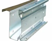
Galvanised profiles should remain in an environment consistent with the coating selection. In the opening area, the risk of moisture may differ from conditions in the wall field. It is worth limiting places where water can accumulate and ensuring access for inspection. Omegas used under flashings also require correct fixing and edge protection after processing in accordance with the documentation.
Acceptance covers geometry and completeness
Before installing the cladding, the dimensions of the opening, verticals, horizontals and planes are checked. Then the connections and conformity of the profiles used are inspected. It is good practice to resolve discrepancies before panels and flashings are installed. Later correction usually involves a greater scope. Deviations should not be concealed by stretching thin elements.
Channels can be a convenient material for creating orderly surrounds. In combination with proper details, they help adapt the structure to the cladding. The condition is a clear division of loads and functions. Cold-formed Z, C, sigma and omega profiles form a diverse set of tools. Each should be used where it meets the actual requirements.
7 branches. Materials closer to your project.
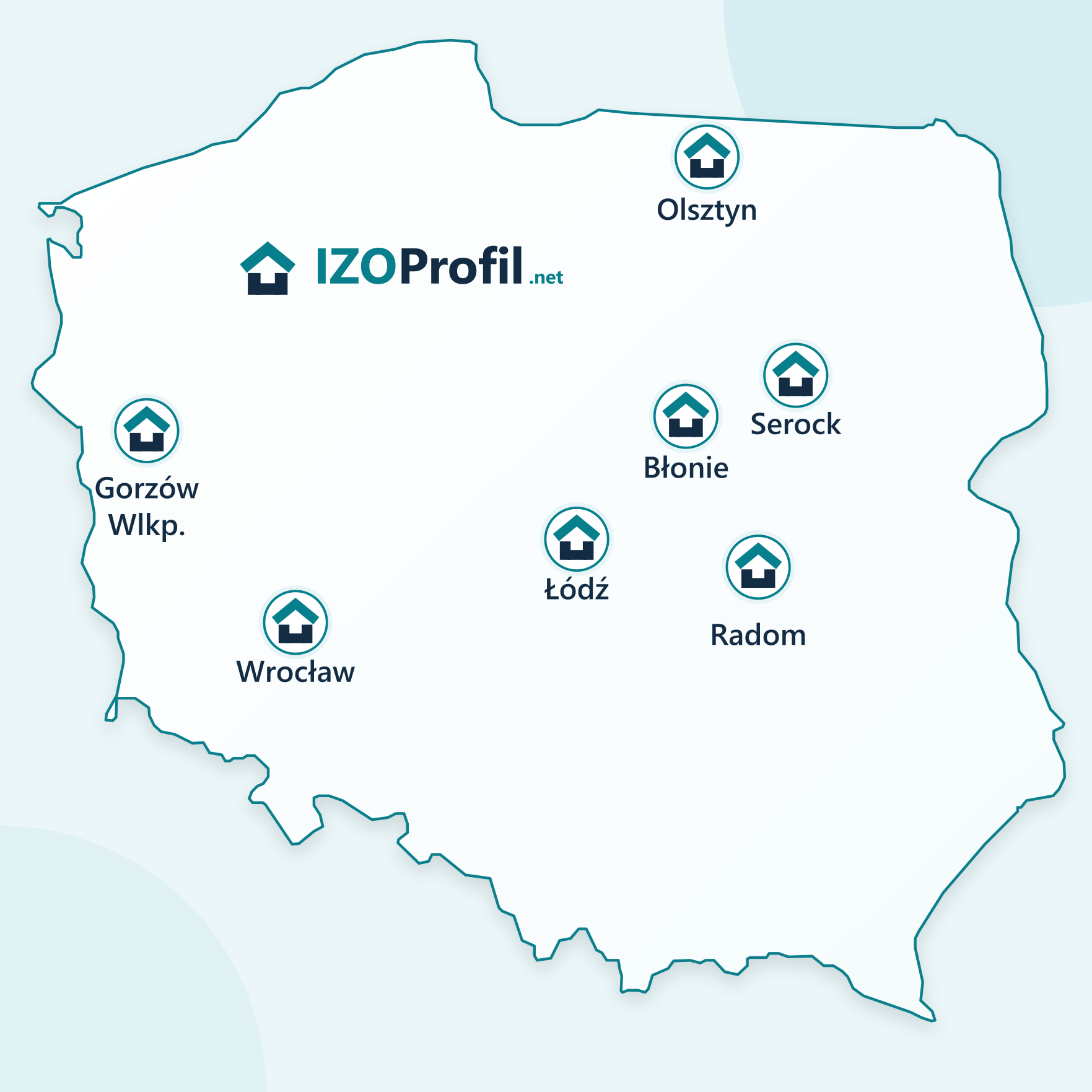
- SEROCK — Dzierżenin 34 E
- BŁONIE — ul. Sochaczewska 138A
- RADOM — ul. Grobickiego 8
- ŁÓDŹ — Natolin 8
- OLSZTYN — Barczewo, ul. Prosta 9
- WROCŁAW — ul. Jerzmanowska 10C
- GORZÓW WLKP. — ul. Zielona 33/34