Flashings
Measuring a starter profile: how to identify the section you need
In brief
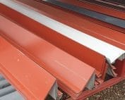
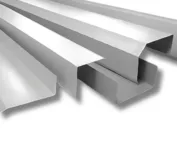
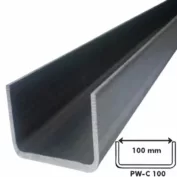
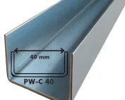
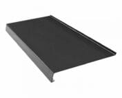
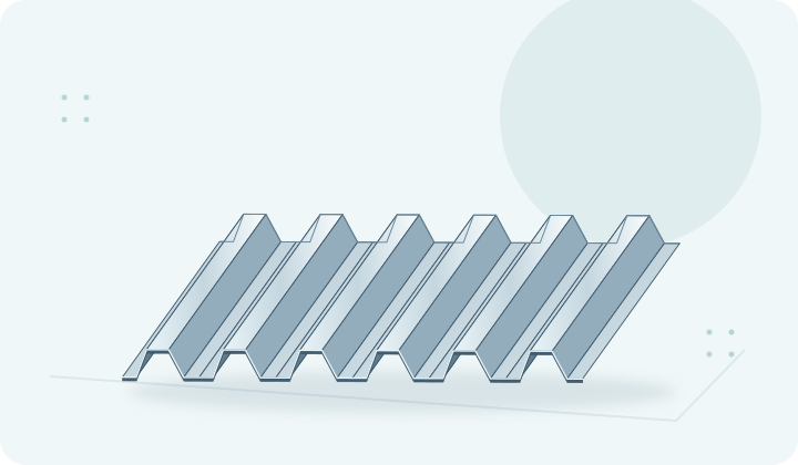
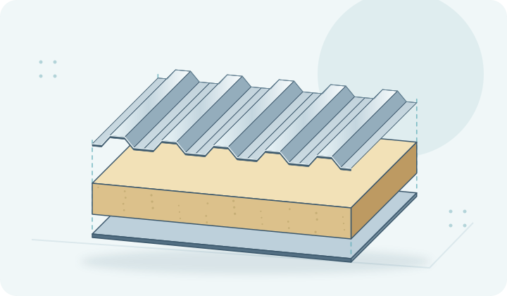
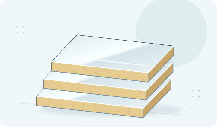
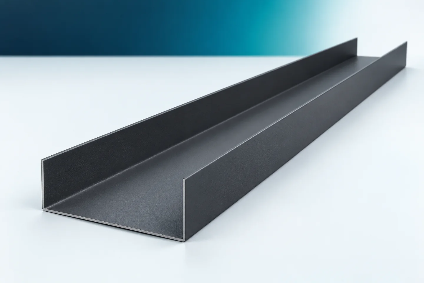
In an order, the term starter profile can refer to several different parts. In one case it is the hook for the first section of the covering. In another it is the component that starts a wall of panels or a trim at the plinth. These profiles are not interchangeable. Measurement must therefore be preceded by a description of the location and function. Only then are the widths of the flanges, the heights of the legs and the bending directions determined. Data prepared in this way help to avoid buying sheet metal that fits in name only. The most important information concerns the type of covering or cladding. It is necessary to state whether the profile works with a standing seam panel, a sandwich panel or another cladding. Each system may have its own connection geometry. Even similar external dimensions do not ensure compatibility of the hook or support.
Name the system in which the profile works
It is worth marking the adjacent element on the sketch. Without it, it is difficult to assess why a specific bend was made. Starter profiles should be described in the context of the entire detail. The manufacturer of folded sheet metal can reproduce the cross-section, but needs clear data to avoid a mistake in its orientation.
Separate the installation function from the load-bearing function
The strip that facilitates setting the first row does not have to carry the weight of the entire wall. This is determined by the system and structure documentation. Similarly, a thin cover can only protect the lower edge. The profile dimensions should not be determined on the assumption that every flange is a load-bearing element.
If support is required, the correct detail and method of fixing must be specified. The designed element should not be replaced with an accidentally thicker flashing. Such a change may not solve the issue of loads or fasteners. The measurement serves to replicate the solution, not to calculate it independently.
Dimensions at the base
At the lower edge of the wall, the position of the cladding relative to the base plate or plinth is measured. Their widths, heights and offsets are important. The intended surface finish must be taken into account. A profile matched to the raw masonry may turn out to be too short after additional layers are applied.
The outer side and the direction of drainage must be marked. If the detail includes a drip edge, its offset should result from the cross-section. In a ventilated system, space for the air inlet may be needed. In a wall with sandwich panels, the provided seals and continuity of insulation are important.
Dimensions at the roof eaves
The starting profile for roof covering may have a hook edge. Its geometry must match the end of the sheet. Not only the lengths of the arms count, but also the clearances and directions of bends. A random strip of similar material does not necessarily maintain a correct connection.
In such a place, starting profiles may work with a gutter apron or combine several functions in one element. These solutions must be distinguished. The drawing should show the position of the gutter and the end of the covering. Without this, the profile can easily be reversed or installed at the wrong height.

Tolerance and installation space
A well-fitted profile does not mean a part made without any installation clearance. The system requirements and substrate tolerances must be taken into account. A too tight element may force pressing in or damage the coating of the adjacent part. Too large a gap may also be incorrect.
It is worth checking access for fastening and the sequence of work. Some surfaces cease to be accessible after the next element is positioned. The cross-section drawing should therefore be supplemented with a description of the installation. Unusual flashings must also be assessed for the possibility of their physical fitting.
Lengths, corners and material
The schedule should separate straight sections from corners and terminations at openings. At these points, different cuts and connections occur. Lengths are selected taking into account the intended method of connection and transport conditions. One long strip will not always be the most convenient solution on site.
The material is described by the type of sheet, thickness and coating. Galvanised, aluzinc and coated sheets may serve different applications. In the case of colour, the visible side and the finish must be specified. These data should remain linked to the number of the specific profile drawing.
How to check the complete set before ordering?
Go through each bend on the cross-section and check whether it has a dimension and direction. Then compare the profile with the adjacent element. For series application, a trial fit of a short section is helpful. It allows detection of a lack of space for a seal or an incorrect side of the hook.
Ridge caps, barge flashings and chimney flashings should receive separate designations in the schedule. Gutter aprons should also not be placed in one item with every starting strip. A clear division helps during production, acceptance and installation. It also reduces the risk of mixing up similarly looking parts.
Questions and answers
Is it enough to order a starting profile for a panel of a given thickness?
Not always. You need to know the joint type, the installation layout and the base detail. The panel thickness alone does not define the entire profile geometry.
Can the starter strip also serve as a gutter apron?
In selected solutions, one component combines several functions. This must follow from its cross-section and the roofing documentation. It does not apply to every starter profile.
7 branches. Materials closer to your project.
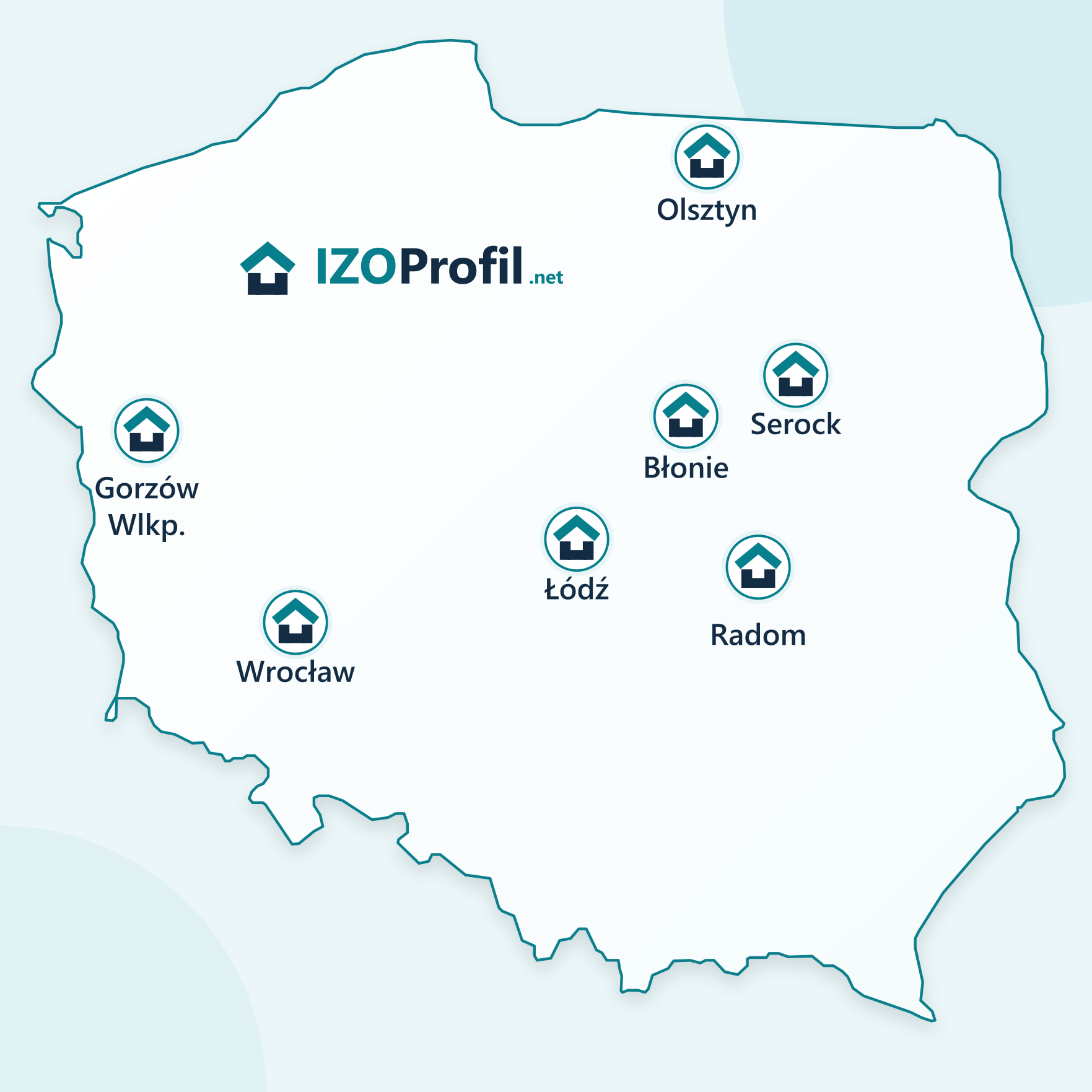
- SEROCK — Dzierżenin 34 E
- BŁONIE — ul. Sochaczewska 138A
- RADOM — ul. Grobickiego 8
- ŁÓDŹ — Natolin 8
- OLSZTYN — Barczewo, ul. Prosta 9
- WROCŁAW — ul. Jerzmanowska 10C
- GORZÓW WLKP. — ul. Zielona 33/34