Sheet metal flashings
Measuring a roof valley: where the two roof slopes meet
In brief
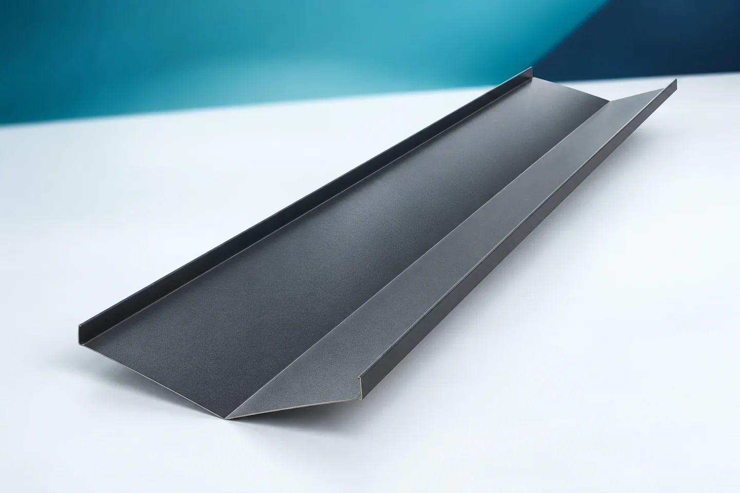
The valley gutter works at the point where water from two parts of the roof arrives. Measuring its length is only the beginning of the preparation. You need to identify the layout of the slopes, the line of their intersection and how the covering is finished. The area from which the water flows also matters. Not every pair of slopes forms the same angle and the same detail. A well-described valley allows the flashing to be selected without accidentally narrowing the channel during installation. On the plan, mark both slopes and the line of their intersection. Add the flow directions and any obstacles that may change the path of the water. A dormer, chimney or roof break affects the local layout. The length of the valley alone does not show how much of the slopes the flashing has to serve.
Start with the roof plan
Such a sketch does not replace drainage calculations if these are required. It does, however, help gather the data for a proper assessment. On a complex roof it is worth numbering the individual roof valleys. This ensures that measurements and orders do not refer to a vaguely described left-hand or rear section.
It is also worth marking the points where water from an additional roof section reaches the roof valley. Such an inflow may be present on one side only. The symmetrical appearance of the drawing should not obscure the actual, uneven supply pattern to the roof valley.
Measure the course and angle where the slopes meet
The roof valley should be measured along its actual line. The length in plan projection may differ from the length on the pitched roof. A cross-section showing the position of both roof slopes is also needed. With different pitches, the profile may require an asymmetrical solution.
The angle dimensioning should be unambiguous. It should be marked on the drawing and not left as a numerical value in the description alone. For a bent flashing, it matters whether the internal angle of the finished profile is meant or the deviation from the flat blank. This is a frequent source of production errors.
Leave room for water flow
The geometry of the roof valley must take into account the distance between the ends of the covering. This space forms the visible drainage channel. It should not be determined solely by the expected visible width of the sheet. The roof conditions and the requirements of the covering system are important.
Sheets protruding too far can restrict the channel. Excessive setback also alters the cover of the detail. Dimensions should therefore be agreed before cutting. The roof valley flashings, their support and the edges of the adjacent sheets should form one planned layout.
Different coverings require different edges
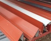
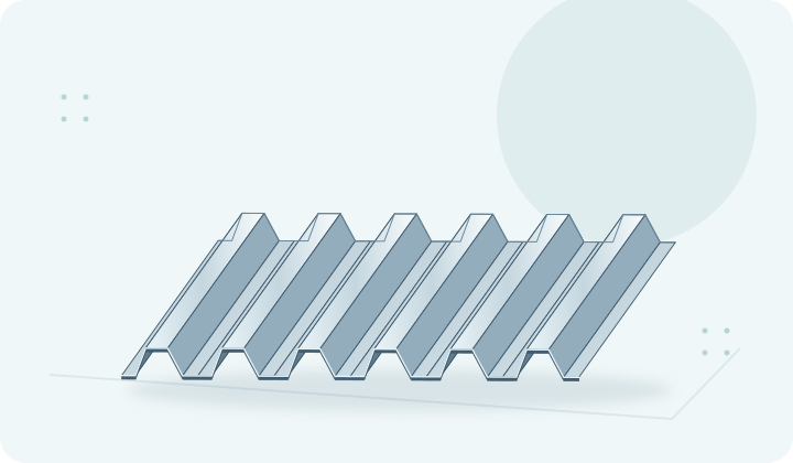
Tile-effect metal roofing, trapezoidal steel sheet and standing seam panels may have a different termination at the roof valley. The profile of the flashing is sometimes provided with bends or edges intended for a specific type of connection. These should not be removed simply because they get in the way when another material is used.
When measuring, record the height and direction of the covering profile. It is worth indicating how its edge parts are fixed. The sealing must also match the geometry. Non-standard flashings should be produced on the basis of this set of data, and not by arbitrarily enlarging a catalogue drawing.

Joints along the roof valley
Individual sections are joined in the manner intended for the given system, often with a lap. In such a layout, the size of the laps and the sequence of installation are matched to the solution and the conditions of the roof slope. In the schedule, the covered length should be separated from the nominal length of the part. Without this, there may be insufficient material at the end of the roof valley for a correct connection.
It is worth drawing the points of contact, particularly where the direction or pitch changes. The connection should not create an unplanned barrier for water. The method of fixing should protect the tightness of the drainage path. Drilling through the base of the roof valley by accident is not a solution to a protruding edge.
Outlet at the eaves
The roof valley must discharge water into the downstream drainage system. The drawing should show the position of the gutter and the gutter apron. Gutter aprons may require a suitable connection to the end of the roof valley. Without this, a correct cross-section above does not guarantee correct water behaviour at the bottom.
At the lower corner, the verge flashings or starter profiles of the given covering often also meet. The sequence of these parts must be established. Ridge caps and chimney flashings belong to other zones but can change the local inflow of water. The entire junction is worth showing on an additional three-dimensional sketch.
Material and order preparation
Attach the type of sheet metal, thickness, finish and number of pieces to the drawing. Galvanised, aluzinc and coated sheets must be clearly identified. The colour of the roof valley may match the roof slope, but its parameters and suitability for the operating conditions must be established first.
Before production, check that each section has a number and a specified termination. For a difficult junction, a trial fitting of a test part is useful. After installation, swarf and material remnants must be removed. The free flow of the roof valley and the condition of the coating are just as important as the conformity of its dimensions with the drawing.
Questions and answers
Can the length of the roof valley be read solely from the roof plan?
Not always. The actual course over the sloping surface must be taken into account. The plan may give a shorter distance than the element needed on site.
Does the same valley profile fit every covering?
No. The edges, clips and sealing method differ. The flashing must be matched to the geometry and the instructions for the given covering.
7 branches. Materials closer to your project.
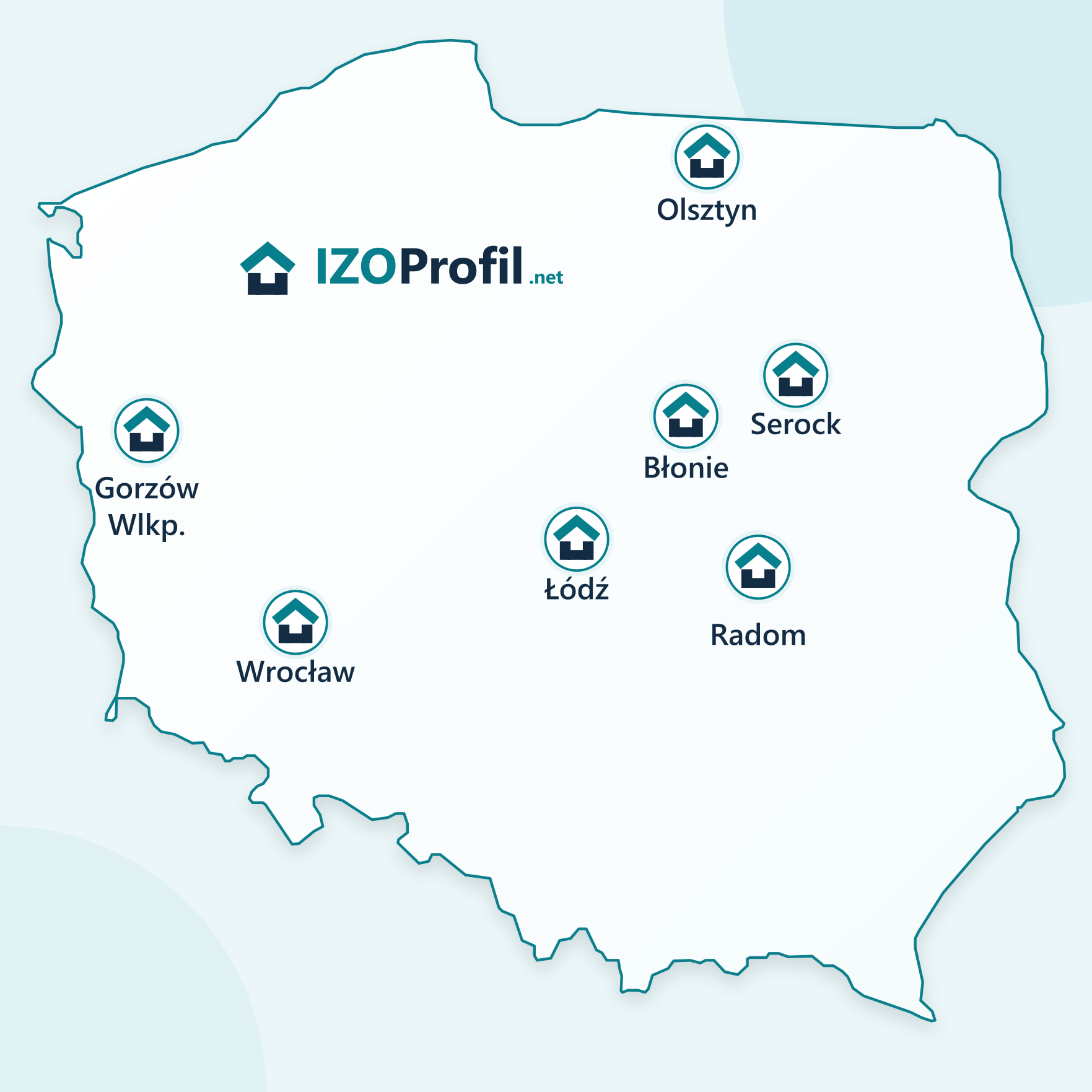
- SEROCK — Dzierżenin 34 E
- BŁONIE — ul. Sochaczewska 138A
- RADOM — ul. Grobickiego 8
- ŁÓDŹ — Natolin 8
- OLSZTYN — Barczewo, ul. Prosta 9
- WROCŁAW — ul. Jerzmanowska 10C
- GORZÓW WLKP. — ul. Zielona 33/34