Profiles and steel structures
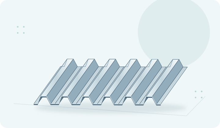
Omega section subframes: coordinating supports, cladding and fixings
In brief
A level grid is not created simply by screwing a row of omega profiles into place. Spacing, the cladding line and the method of fixing to the substrate must be coordinated. Cold-formed profiles form a chain of supports and connections here. Every link matters. Good geometry makes the subsequent work easier, but it must go hand in hand with load-bearing capacity and durability. It is worth preparing these points before drilling the first holes. Omega profiles can be fixed to various elements, but not every fastener is suitable for every substrate. Information is needed on the material, thickness and actual condition of the support. This also applies to refurbishment. An old substrate should not be assessed solely on its visible surface. If its parameters are uncertain, they must be established before adopting a solution.
The substrate must be assessed before selecting the fixing
The profile and the fixing work together. A strong omega profile will not compensate for a weak fixing. Conversely, a large fastener will not remedy a foot that is too thin or incorrect support spacing. Galvanised profiles should be selected with the whole junction in mind. The documentation should specify not only the product but also where and how it is to be used.
The grid spacing should match the cladding
The spacing of the omega profiles results from the requirements of the layer being installed and the loads. The dimensions of the cladding elements, the position of their joints and the required edge support are important. A regular rhythm is often convenient but does not solve every location. Corners, terminations and openings require separate verification. It is worth planning them on an elevation or roof layout drawing.
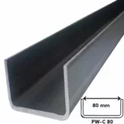
If the design specifies different spacing in individual zones, it must be maintained. Wind load need not be uniform over the entire surface. A convenient module from the central area should not be transferred to all edges. C-sections or other cold-formed profiles may supplement the framing at certain details. Their role should also be described.
A level plane must not come at the cost of deformation
Before installation, the plane of the substrate and the target line of the cladding are checked. If there are deviations, the specified adjustment system must be used. Random shims or pressing the omega profile against irregularities can alter the behaviour of the connection. The feet should be supported in accordance with the detail. A thin profile is not a tool for levelling an arbitrarily curved structure.
It is worth taking measurements at successive stages. An error accumulating over several bays can be difficult to remove once the framing is closed. Galvanised profiles have specified tolerances that must be taken into account together with the deviations of the supports. Measurement does not end with the first element. Checking the entire plane helps achieve repeatable cladding fixing.
The feet and the central section play different roles
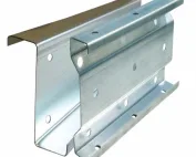
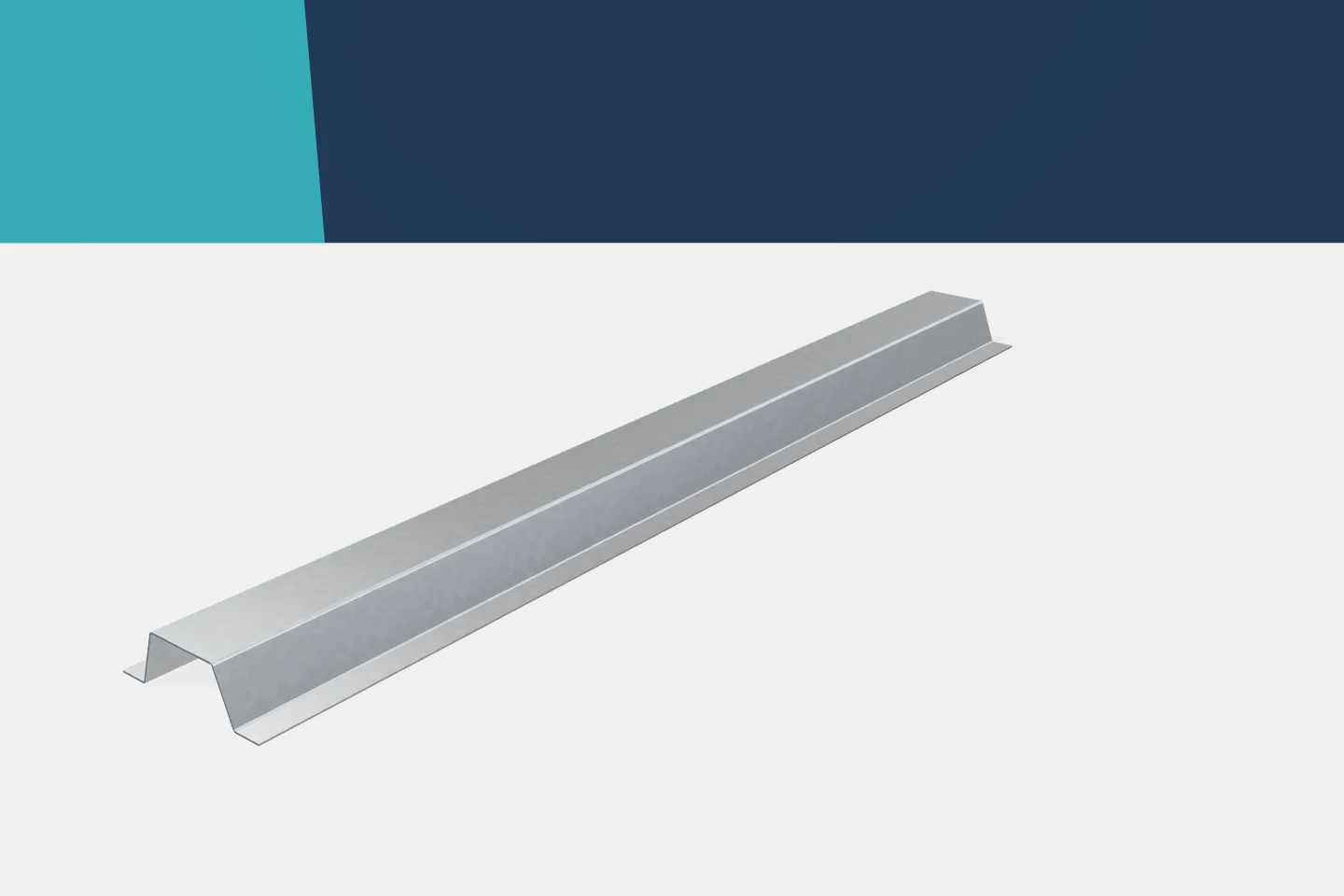
The side feet are used to fix the profile in the specified arrangement. The central part may form the support for the next layer. Holes must be positioned in accordance with the documentation. These zones must not be swapped arbitrarily, nor should the bends be drilled through. The edge distances and the ability to seat the fastener correctly are important. Even a simple framing consists of real load-bearing junctions.
Tool access must also be provided for. Cladding installed later can obscure the connection to the substrate. It is therefore worth completing and inspecting it at the appropriate time. Omegas, zeds and sigma profiles have different fixing planes. A detail prepared for one section does not always fit another. A similar stand-off height is not sufficient for substitution.

The space behind the cladding requires continuity of detail
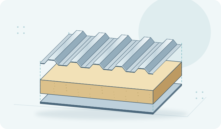
The omega creates an offset layer but does not itself ensure correct ventilation. The air flow path and water drainage must be checked. Horizontal elements may impede these functions in a given arrangement. The solution depends on the construction of the building envelope. Its properties should not be inferred solely from the existence of a gap.
Similarly, steel cannot be regarded as a thermal barrier. Cold-formed profiles conduct heat, so the influence of the substructure requires assessment. If separators are provided, they must be matched to the loads and operating conditions. Material inserted accidentally under the foot may deform over time or alter the contact pressure. The thermal function does not exempt from mechanical requirements.
Surface protection begins during processing
Cutting and drilling may leave swarf and exposed areas. These must be dealt with in accordance with the material and system instructions. Swarf left on the surface may cause soiling or corrosion spots. Coating damage is assessed separately from section deformation. Painting over alone does not solve the problem of a crushed foot.
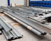
Galvanised profiles should be stored under conditions that limit moisture. This also applies to short omegas, which are easily left in an open carton or on a wet surface. A rusting foreign element should not contaminate the finished surface. It is worth setting aside a processing area and removing waste as work proceeds. These are simple measures that facilitate later acceptance.
Checking the framing precedes cladding installation
Before covering, the spacing, plane and all fixings are checked. The conformity of the profile with the design and the required support at the cladding joints must be confirmed. This is also the moment to assess the gap and details at openings. Once the boards are installed, access will be worse. Early inspection reduces the risk of dismantling the finished surface.
Omegas are practical substructure elements if they correspond to a specific function. A lightweight frame should not be equated with any hat purlin. Channels, Z-sections and sigma profiles also have their own applications. Properly selected cold-formed profiles allow the work of successive teams to be organised. The result depends on the detail connecting the substrate, profile and cladding.
7 branches. Materials closer to your project.
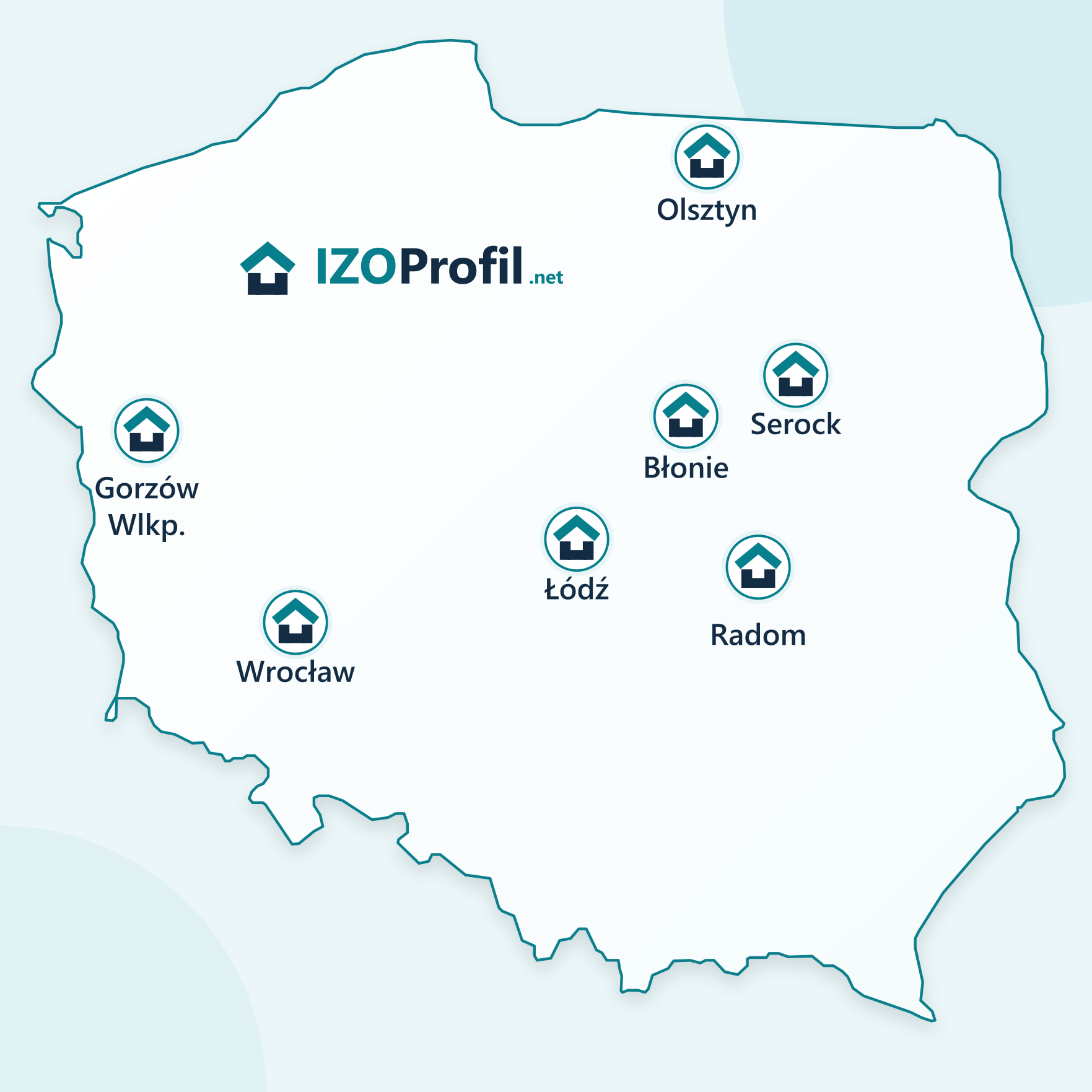
- SEROCK — Dzierżenin 34 E
- BŁONIE — ul. Sochaczewska 138A
- RADOM — ul. Grobickiego 8
- ŁÓDŹ — Natolin 8
- OLSZTYN — Barczewo, ul. Prosta 9
- WROCŁAW — ul. Jerzmanowska 10C
- GORZÓW WLKP. — ul. Zielona 33/34