Flashings
Ordering parapet coping: measuring width, fall and corner details
In brief
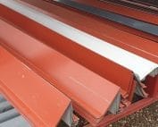
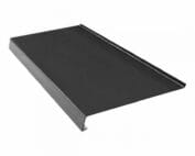
The parapet flashing must cover the top of the wall and drain water in the intended manner. Its width follows from the finished wall cross-section including all layers. The order also requires the leg heights, the direction of fall and the geometry of the corners. A part that fits on a straight run may not resolve the termination at a higher wall. It is therefore worth preparing the measurement as a set of related details. Include the masonry, insulation and finishing layers on both sides. If measuring in advance, the intended thicknesses must be entered on the drawing. The dimension of the base or raw parapet alone is not sufficient. A cap that is too narrow may not ensure the correct position of the side edges.
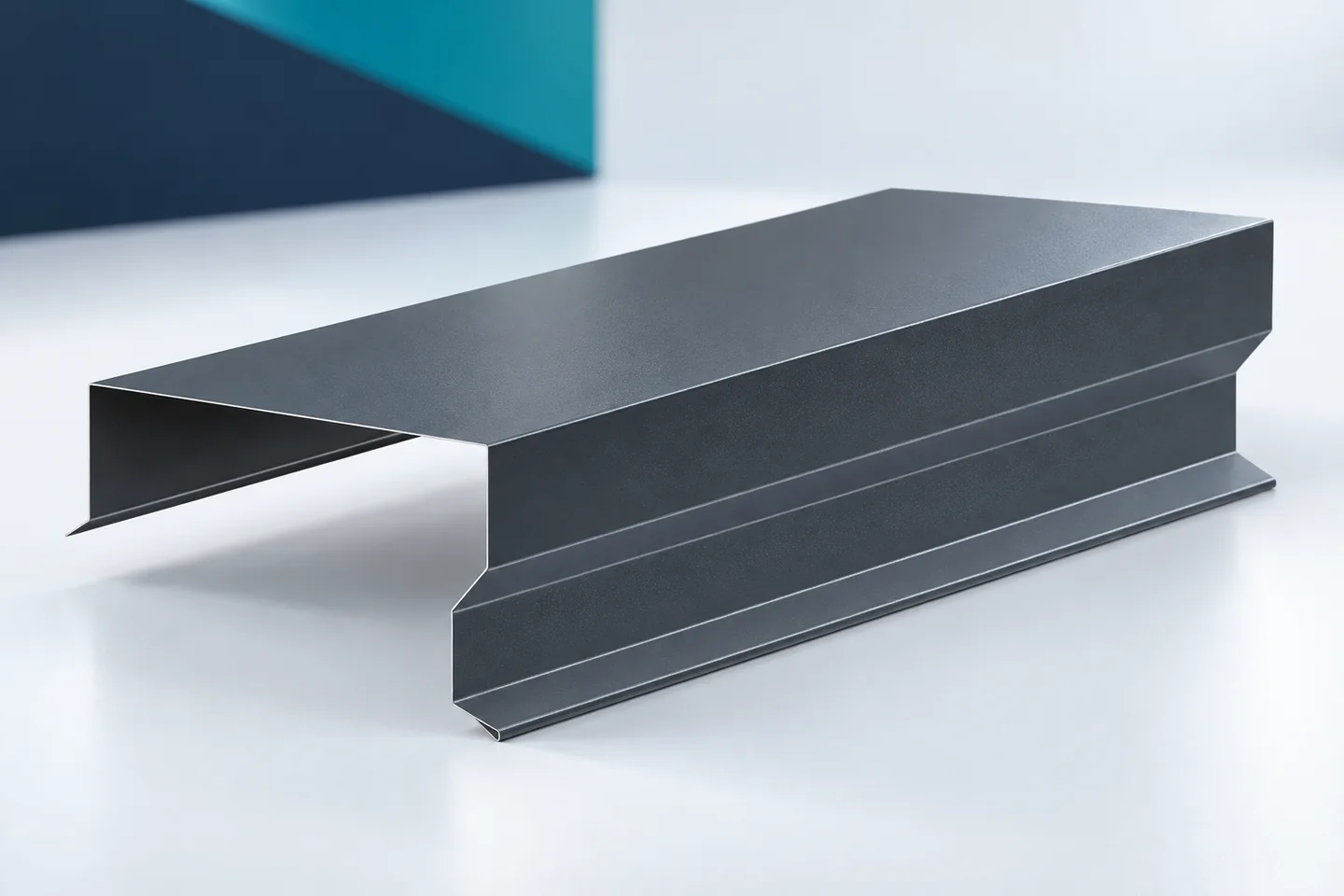
Measure the finished wall thickness
The width should be checked at several points. A parapet does not always have the same cross-section along its entire length. Deviations in the substrate must be identified before production. They should not be concealed by forcibly bending finished flashings, as this changes their line and the way water is drained.
Determine the direction of fall
The upper plane of the flashing must lead water away in accordance with the design. The direction and value of the assumed slope must be marked on the cross-section. This prevents confusion between the heights of the two legs. A drawing resembling an inverted letter U does not yet describe the correct solution.
The slope also depends on the preparation of the substrate. Thin sheet metal should not form the required geometry merely through tension between the fixings. Before measuring, it is worth establishing how it will be supported. This allows both the course of the surface and the position for the joints between successive sections to be assessed.
Legs and drip edges
The height of the legs is selected according to the zone being covered and the method of fixing. The lower folds and their direction must be specified. The drip edge should drain water at an appropriate distance from the façade. Folding the edge alone is not enough if the entire profile ends too close to the wall.
It is worth marking the point from which the projection is measured. The distance from the bare masonry and from the finished render are different values. With thick insulation, this difference is significant. Bespoke flashings allow the legs to be adjusted, but they require correct data on all layers.
The corner is a separate geometric element
On the plan, the corner angle and the widths of the adjacent parapet sections must be given. It is not always a right angle. Where the wall width changes, an additional transition is required. This detail cannot be described solely by a single cross-section of the parapet cap.
The method of connecting the corner parts to the straight sections must be established. The continuity of the covering and the course of the drainage are important. A well-prepared sketch shows the visible edges and terminations. It also allows the appearance of the corner to be planned before there is any need for ad-hoc cutting of material on site.

Lengths and material behaviour
A long run of flashings must be divided into sections in accordance with the installation solution. Sheet metal changes dimensions with temperature, and the connections should account for this. All parts should not be joined independently into one rigid strip. The fastening detail must correspond to the width and the conditions of the detail.
In the schedule, give the nominal length of each part and the number of pieces. Show the zones of overlaps or other intended connections separately. A longer section reduces the number of joints but requires transport and support. The decision on length should also take into account access on the roof.
Coating over a wide surface
Parapet caps can be made from galvanised, aluzinc or coated steel sheets. The material is selected according to the environment and the requirements of the building. For a coloured finish, the shade, texture and gloss must be specified. A wide surface can expose differences between batches of material.
Mark the outer side on the cross-section. In an asymmetrical profile, reversing it can mean an incorrect slope and incorrect positioning of the legs. It is advisable to agree a surface sample before ordering. A colour viewed on a screen does not guarantee an identical effect on the façade.
Checking the entire perimeter
Before approving the drawings, go through the schedule from the first corner to the last. Check height changes, gaps and terminations at other walls. Every transition should have a number. Such a check allows a missing part to be found before production begins.
Verge flashings, ridge caps, gutter aprons and chimney flashings can be ordered in parallel, but require separate drawings. Starter profiles also have different functions. Consistent material does not mean a common cross-section. At acceptance, it is worth checking the parapet dimensions and the condition of the edges, which are easily damaged during transport.
If the perimeter contains a technical gap or a transition to another material, its position must be marked. Continuity of colour does not mean that all parts of the wall may be joined with sheet metal. The detail should preserve the required division and the way the adjacent elements work.
Questions and answers
Can a parapet coping have equal legs on both sides?
It can if the detail requires it. With a slope and different cover heights, however, the legs may need different dimensions.
Why do the corners need to be drawn separately?
A section does not show the angle in plan, the direction of the joints or changes in wall width. A separate drawing allows the full node to be made, not just a simple profile.
7 branches. Materials closer to your project.
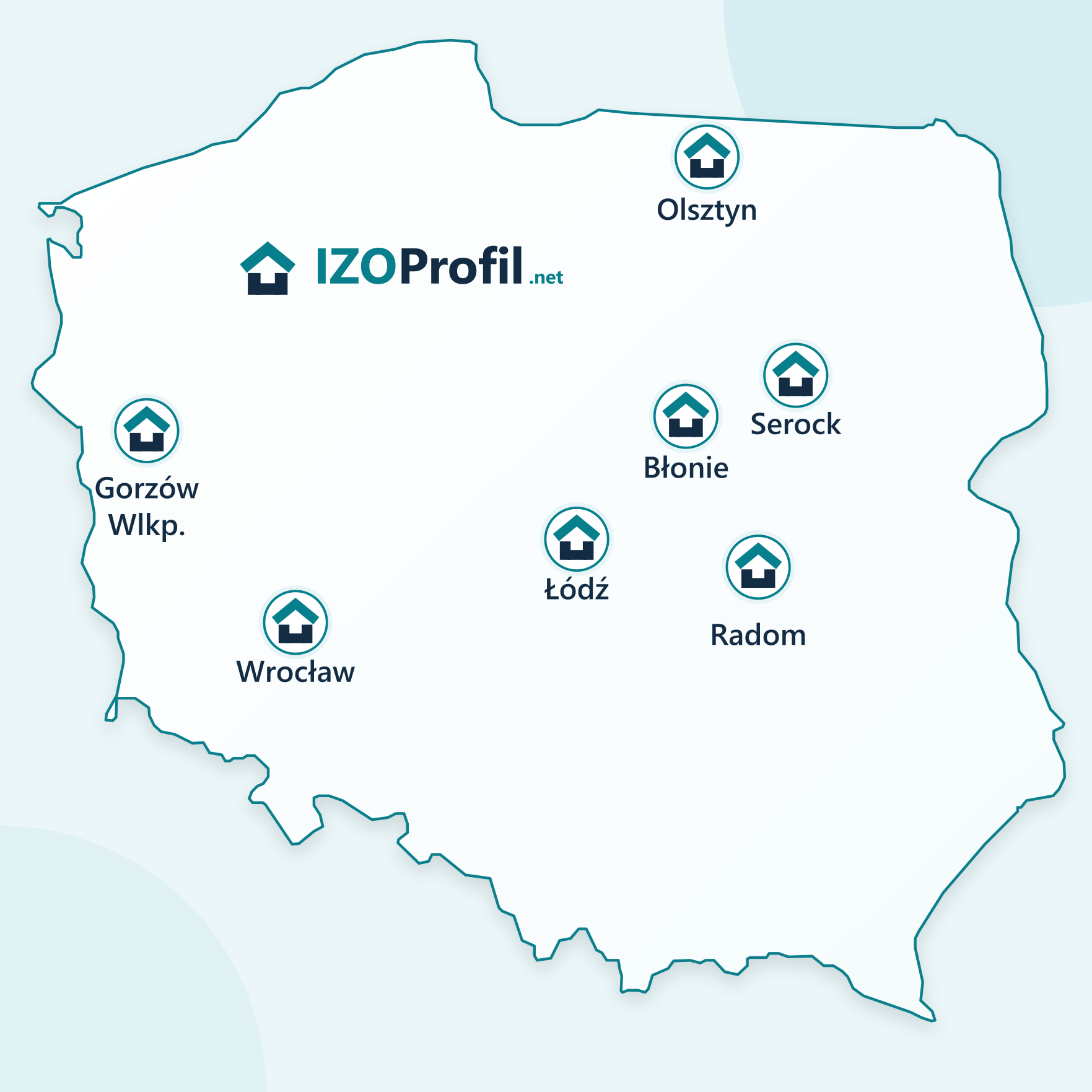
- SEROCK — Dzierżenin 34 E
- BŁONIE — ul. Sochaczewska 138A
- RADOM — ul. Grobickiego 8
- ŁÓDŹ — Natolin 8
- OLSZTYN — Barczewo, ul. Prosta 9
- WROCŁAW — ul. Jerzmanowska 10C
- GORZÓW WLKP. — ul. Zielona 33/34