
Sheet metal flashings
Measuring chimney flashings: why each side needs its own dimensions
In brief
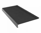
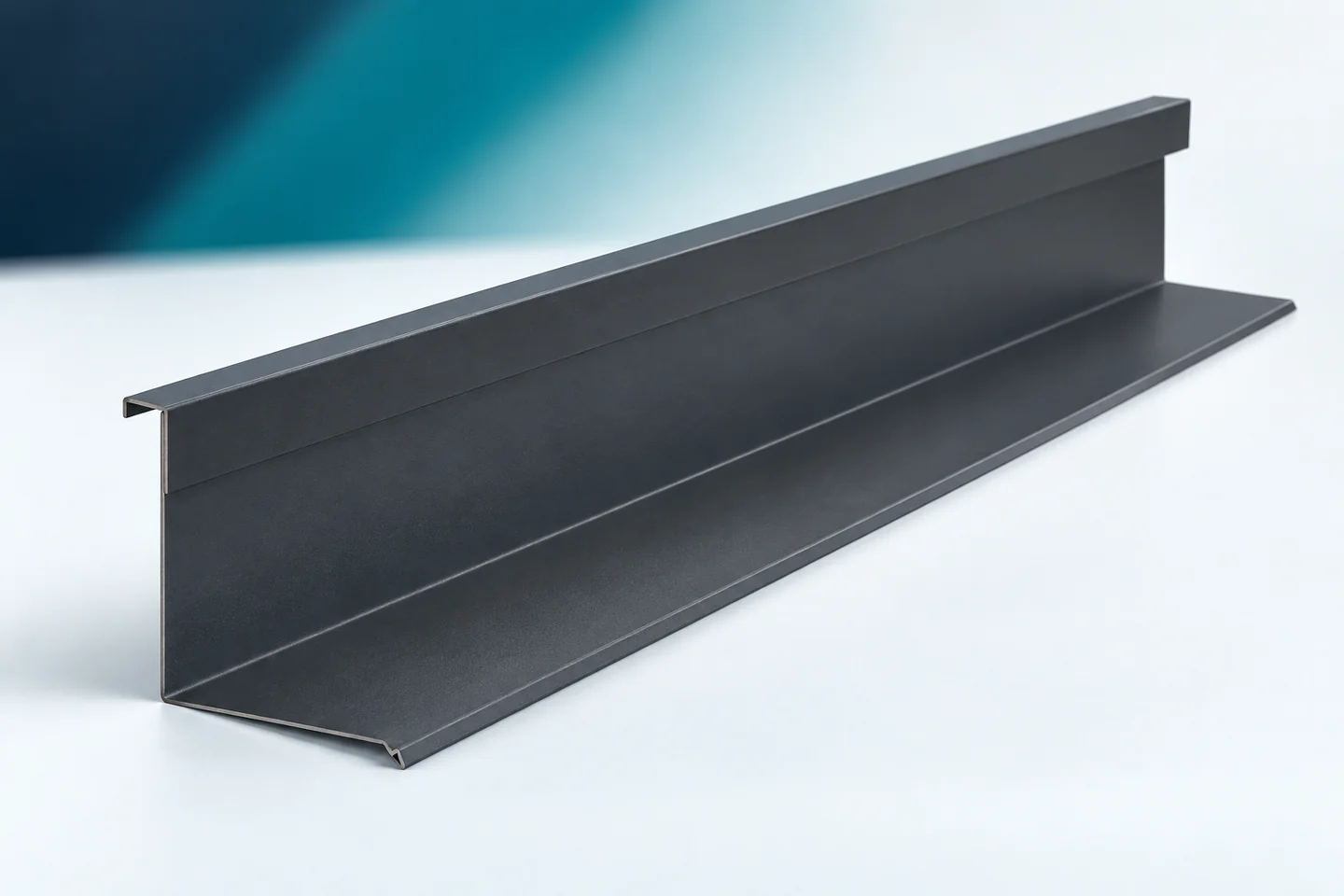
The chimney intersects the roof slope at a specific angle. That is why the flashing on each side sits in a different position. The lower apron directs water onto the covering, the side sections guide it along the walls, and the upper section must handle the runoff from the ridge side. The measurement covers more than the chimney perimeter. The heights at the roof slope, its pitch and the connection plan are also needed. A sketch prepared in this way reduces the number of corrections that have to be made on the roof. Dimensions should be referenced to the final covering surface. A measurement taken before the battens or the sheet profile are laid may give a different height for the detail. On the sketch it is worth marking the slope line and the direction to the ridge. This allows the front and rear sides of the chimney to be clearly identified.
Establish the reference level
The intended finish of the chimney walls must also be taken into account. Render or cladding changes its external dimension. Chimney flashings measured to the bare masonry may not fit once the layers are applied. If the finish is not yet in place, its anticipated thickness must be clearly described.
Chimney dimensions in two directions
Measure the width across the slope and the length along the roof pitch. Also check the corner angles and any unevenness. A chimney does not always form a perfect rectangle. For a renovation, it is worth comparing several heights, particularly when its surface has offsets or additional casing.
The perimeter should not be equated with the length of the finished flashings. Joints require overlaps, bends and terminations. These pieces of material must be included in the drawing. Giving only the four wall lengths does not provide the manufacturer with a complete basis for producing a complete set.
The description of four sides applies to a chimney with a suitably shaped casing. A round flue penetration requires a different solution, for example a collar designed for it. The dimensions of a rectangular apron should not be transferred to every type of roof penetration.
Side elements account for the slope
On both sides of the chimney, the line of contact with the roof pitch is inclined. The height of the flashing above the covering should be specified in relation to this run. A simple rectangular strip may require appropriate preparation. It should not be assumed that an identical height measured from the horizontal corresponds to the entire length of the side.
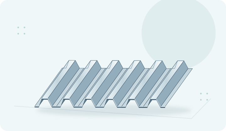
On the side sketches, also show the covering profile. A high rib or standing seam affects how the flashing transitions. The detail depends on the system. Chimney flashings for a popular tile-effect metal roofing do not have to look the same as components intended for flat roof panels.
Lower apron and upper runoff
The lower section should direct water onto the intended covering surface. The upper side of the chimney must take the runoff from the roof slope. When measuring it, the available space and the way water is directed to the sides matter. The width of this zone does not result solely from the dimension of the chimney wall.
For a wide obstruction or a complex intersection of roof slopes, an individual drainage detail may be required. Non-standard flashings should then be produced on the basis of an agreed solution. Merely adding a wider flange without controlling the slope can create a place where water is retained.

Flashing-to-wall junction
The drawing should show how the upper edge of the sheet at the chimney is covered. This may be a suitable trim or another solution provided for the given arrangement. The type of substrate and the method of fixing must be taken into account. It must not be assumed that every chimney can be flashed identically.
It is also important to maintain the required clearances and the rules for penetrating the roof. This information comes from the design and the chimney documentation. Measuring the flashing does not replace checking them. The sheet layout should also account for any movement of the covering relative to the wall, in accordance with the system solution.
Material and visible surfaces
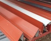
Chimney flashings can be made from galvanised, aluzinc and coated steel sheets. The choice is determined by the conditions and compatibility with the covering and sealants. For coloured material, mark the outer side on each component. After bending, part of the surface may end up in a visible place.
The thickness should not be selected solely according to what is easier to bend on site. It must correspond to the function and the possibilities of producing the profile. In the schedule, it is worth giving a common material description and, for each part, its number. This makes it easier to check the conformity of the entire set after delivery.
Check the completeness of the set
On the drawing, trace the path of water from the ridge side to the lower apron. Mark the sequence in which the parts are laid and their joints. Also take into account the underlay. The visible sheet does not take over all the tasks associated with sealing the penetration through the roof slope.
Ridge tiles and barge boards in the vicinity may affect access for the works. Eaves courses take the water at the end of the slope, and starter profiles belong to other junctions. Each component must be listed separately. A complete chimney flashing schedule should allow all sides to be identified without guessing.
Questions and answers
Is measuring the chimney perimeter enough to make the flashings?
No. The roof pitch, the position of the covering, the outlet heights and the way the joints and terminations are made are also needed.
Are the side flashings of a chimney always the same?
They do not have to be. The geometry of the roof slope, the direction of the covering profile and the connection detail all have an influence. Both sides should be dimensioned and marked separately.
7 branches. Materials closer to your project.
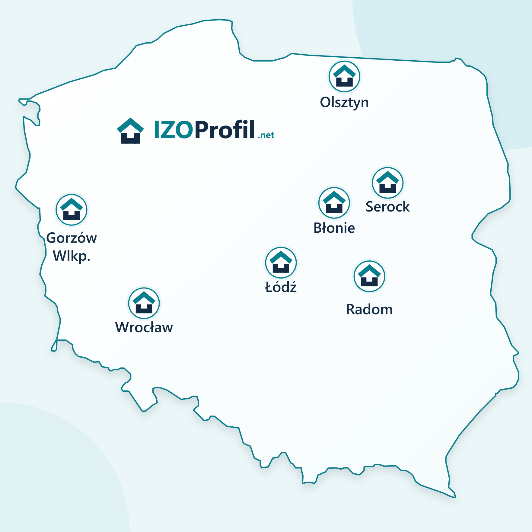
- SEROCK — Dzierżenin 34 E
- BŁONIE — ul. Sochaczewska 138A
- RADOM — ul. Grobickiego 8
- ŁÓDŹ — Natolin 8
- OLSZTYN — Barczewo, ul. Prosta 9
- WROCŁAW — ul. Jerzmanowska 10C
- GORZÓW WLKP. — ul. Zielona 33/34