Sheet metal flashings
Measuring a barge flashing: recording leg lengths, folds and orientation
In brief
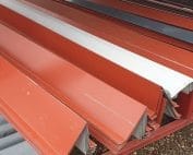
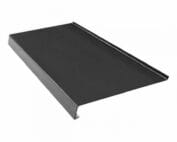
Verge flashings are ordered for a specific roof edge. Their fit is determined by the position of the outermost sheet, the profile height and the way the gable is covered. The dimension of the board alone is not enough. The run of the upper arm and the lower termination must also be established. A clear cross-section allows the finished product to be compared with the actual detail. It also makes it easier to order a bespoke flashing when standard dimensions do not match the building. The reference point should be the position of the final covering. A measurement taken solely on the structure may not account for the height of the battens and the sheet profile. If the covering is yet to be laid, data on its layers is needed. The verge flashing must fit the final assembly, not the temporary state of works.
Start from the finished roof slope plane
On the sketch, mark the sheet edge and the gable side. It is worth indicating whether the outermost profile ends at the ridge or elsewhere. This information affects the layout of the flashing. A photo can supplement the drawing but should not replace a dimensioned section.
Measure the upper and side arms separately
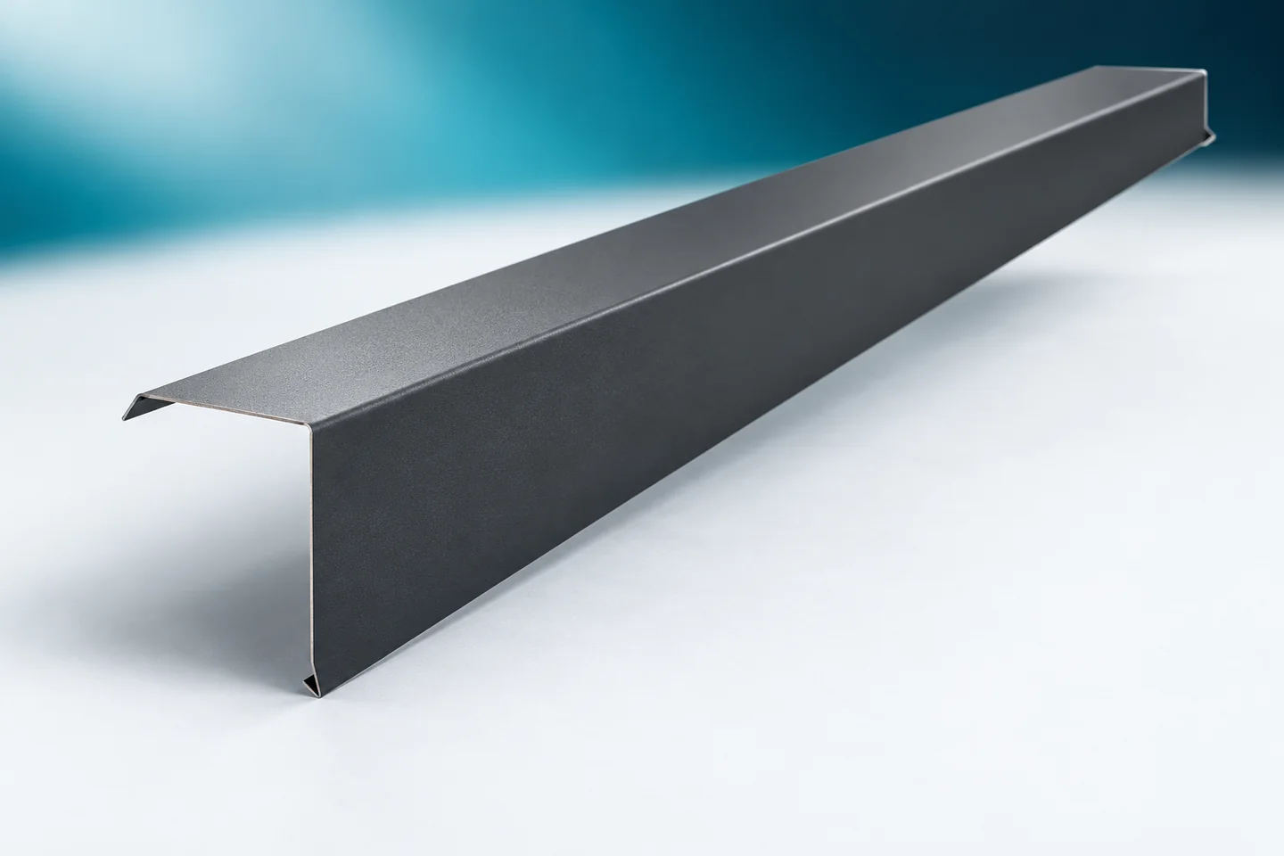
The upper arm is responsible for covering the area next to the covering. The side arm covers a specific section of the gable. Their lengths do not have to be equal. The angles and any offsets must also be specified. The description ‘wide verge flashing’ is too general for producing a repeatable component.
Dimensions must be applied from clearly defined points. If you give an external distance, mark this on the sketch. The manufacturer takes the bending process and tool radii into account. The material development should not be guessed by simply adding dimensions without establishing how they are measured.
What does the lower edge do?
The end of the side arm may include a hem or a drip edge. Such a bend affects the rigidity of the edge and the behaviour of running water. It must be drawn in the correct direction. Two similar bends can result in different positions of the lower edge relative to the façade.
When renovating, the new thickness of the wall finish must be taken into account. Verge flashings selected before insulation may end too close to its face. Measuring the current detail is safer than copying the old section. It also helps to reduce later cutting and bending of the edge.
Right and left sides are not always interchangeable
Some verge flashings are part of a system with a channel or an additional clip. They may be available in left-hand and right-hand variants. The method of specifying the side should be checked in the documentation. Specifying right without giving the viewing direction easily leads to misunderstanding.
An arrow pointing towards the ridge and the external side of the building can be marked on the drawing. This keeps the position of the profile clear. It should not be assumed that a finished component can simply be turned over. The position of the bends will change, and sometimes also the side of the coating.

Draw the connection to the eaves and ridge
The verge flashing does not stop halfway up the roof slope. At the bottom it must work with the eaves detail, and at the top with the closure of the gable at the ridge. The gutter aprons and ridge caps may require appropriate termination of the adjacent flashing. It must be established which parts overlap.
For unusual geometry, it is worth making a separate sketch of the corner. A cross-section does not show how the end of a long component is cut. Unusual flashings can thereby be ordered as a well-thought-out set. This avoids makeshift covers made from offcuts.
In the schedule, plain parts and prepared ends can be separated. This makes it clear which sections require a specific cut and which remain full. This is also important for packing and labelling components intended for opposite gables.
Material and length division
The length of the gable should be planned taking joints into account. A long component can reduce the number of joints but requires appropriate support when handling. The possibility of transport to the site should also be checked. Dimensions favourable for production are not always convenient for installation.
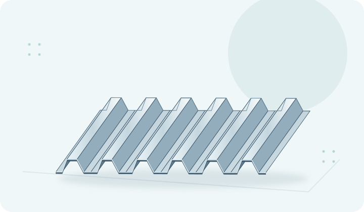
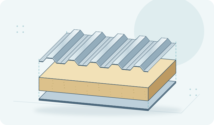
Add the thickness and type of steel sheet to the schedule. Galvanised, aluzinc and coloured coating mean different surface protection. For coated material, the gloss or texture must be specified. The colour of the verge flashing can be matched to the roof or the façade, but the decision must be made before the production run.
Drawing and sample check
Before approval, check that the drawing includes all arms and bend directions. It is worth comparing it with measurements taken at several points on the gable. An uneven structure may require improvement of the substrate. It should not be expected that thin sheet metal will level out any deviation.
Starting profiles and chimney flashings have different measuring points, even when they come from the same order. Each type should receive its own designation. This makes it easy to check the number of pieces and the conformity of the cross-section on delivery. This is simpler than identifying all components only on the roof.
Questions and answers
Can a verge flashing be ordered from a photo alone?
A photo helps identify the detail, but it does not provide reliable dimensions and angles. A cross-section with a description of the mounting side is needed for production.
What should be marked on an asymmetrical component?
The outer side, the direction to the ridge, the coated side and the dimensions of all arms. It is also worth establishing what the manufacturer calls the left and right variants.
7 branches. Materials closer to your project.
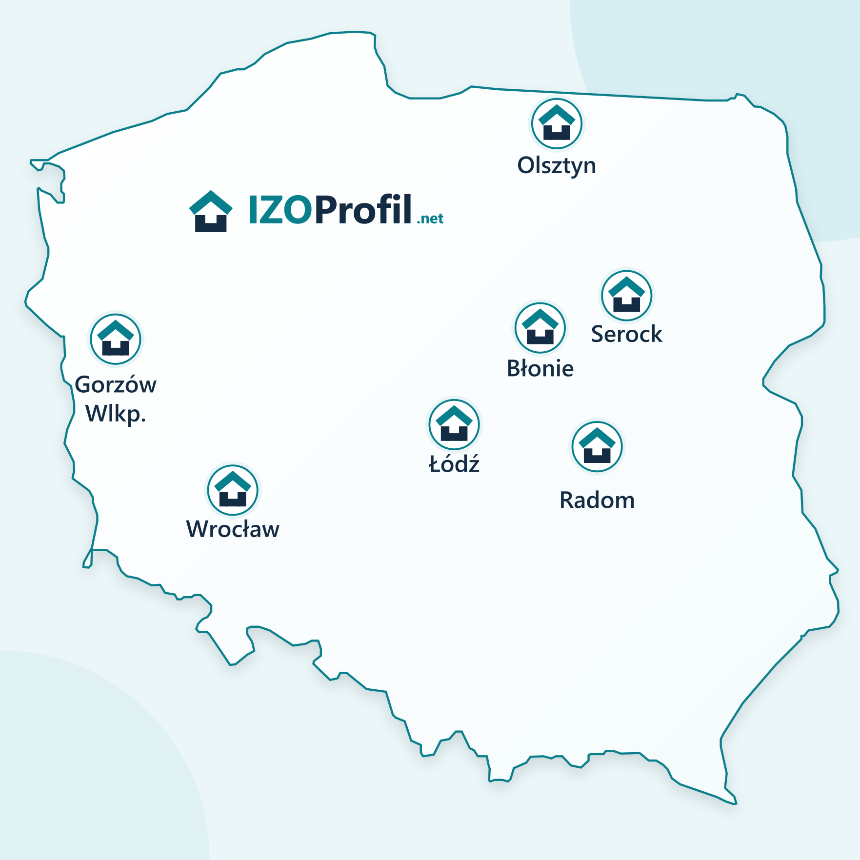
- SEROCK — Dzierżenin 34 E
- BŁONIE — ul. Sochaczewska 138A
- RADOM — ul. Grobickiego 8
- ŁÓDŹ — Natolin 8
- OLSZTYN — Barczewo, ul. Prosta 9
- WROCŁAW — ul. Jerzmanowska 10C
- GORZÓW WLKP. — ul. Zielona 33/34