Profiles and steel structures
Bolts, splice plates and bracing: preparing a steel section installation list
In brief
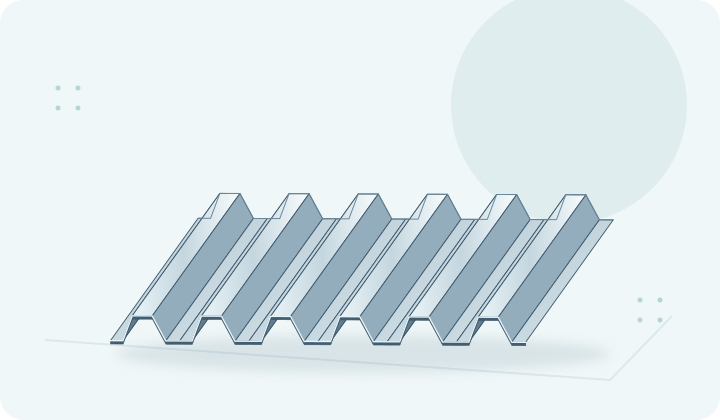
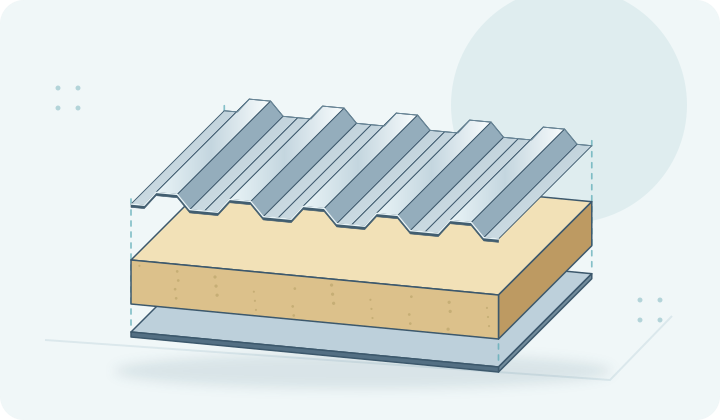
The absence of a single type of connector can bring the installation of an entire purlin line to a halt. That is why it is worth treating the steel order as a set of parts for building specific connections. Cold-formed profiles are its main component, but not the only one. Z-sections, C-sections and sigmas need the right connections. Omegas require matching fixings. A good installation list combines all these elements with the work plan. A schedule of profile metres alone does not show the scope of work. Details of supports, span connections and bracing are also needed. Each detail should have defined component parts. It is worth assigning them to drawing numbers and building zones. Then it can be checked whether the material list covers everything needed for installation.
The list should be derived from the connection detail drawings
Galvanised profiles may be supplied together with some accessories, but the scope is not obvious. It should not be assumed that screws or intermediate plates are always included in the price. This must be confirmed in the quote. Missing items should be identified before ordering. This avoids a situation where both parties believe that a given element is supplied by someone else.
A connector is described by its full designation
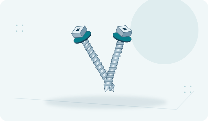
Diameter and length do not exhaust the description of a screw. Its grade, the type of assembly and the intended protection are also important. Likewise, a screw requires compatibility with the material and the thickness of the support. A product for fixing cladding does not have to be suitable for a structural connection. The list should reduce the possibility of confusing similar parts.
It is not worth writing a general entry such as “screws for C-sections”. The contractor needs information consistent with the design. Nuts and washers are also important if they have been specified. If availability changes, a replacement must be agreed. Cold-formed profiles are sensitive to local connection conditions, so an arbitrary set from the warehouse is not an equivalent solution.
A splice plate is not just any piece of steel
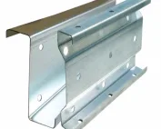
In a configuration with splice plates, their geometry and length follow from the structural solution. The hole pattern and thickness also matter. They should not be replaced with random profile offcuts. A similar shape does not prove that the part will provide the intended transfer of forces. Each splice plate should have a marking and an assigned installation location.
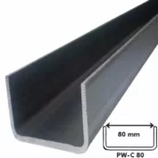
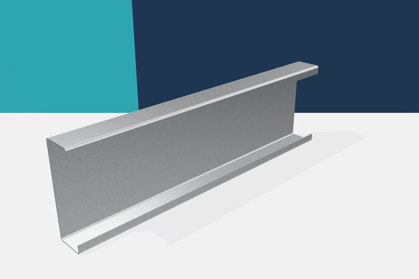
Z-sections can also form lap connections, while C-sections use appropriate intermediate elements. Sigma profiles require a detail matched to the folded web. These solutions are not interchangeable. In the schedule, it is worth separating main profiles from connection parts. This makes it easier to check the number of pieces and limits the use of short elements for the wrong purpose.
The support plate determines how reactions are transferred
A connection at the frame or column may include a bracket or an intermediate plate. Its shape and position affect the bearing of the profile. Height, hole arrangement and distance from adjacent elements are important. It is worth checking whether the part is supplied by the main structure contractor or by the profile supplier. The boundary of scopes must be clear.
A bracket should not be treated as a detail that can always be refined on site. Changing its position may require new holes and affect the roof geometry. Galvanised profiles with prefabricated holes should match the agreed connection. Therefore, checking drawing compliance before production is more valuable than quickly finding a solution during installation.

Bracing is specified by function and length
Bracing, ties and other stabilising elements may come in various variants. Their length depends on the geometry of the system, not just on the profile height. The positions and installation sequence specified in the documentation must be maintained. Supplying an approximate number of bars is not enough. Each part should correspond to a specific field or purlin line.
The lack of stabilisation should not be masked by prior installation of the cladding. Its effect must be confirmed for the given solution. Z-sections and C-sections have open cross-sections, so their behaviour depends on lateral support. Omegas mounted under other details do not automatically take over this function. The completeness of small parts is part of the correctness of the entire structure.
Packaging by stage helps the crew
It is worth supplying accessories with a clear description and a link to the drawings. If the construction site is divided into zones, appropriate batches can be prepared. This limits the search for the right elements in many boxes. However, identification must be maintained after opening the packaging. Mixing similar connectors makes later inspection more difficult and increases the risk of error.
A good moment to check the complete set is when preparing the first connection of a given type. The tool access and the conformity of the elements can then be confirmed. This does not replace the design, but it helps detect discrepancies in the delivery or documentation. Cold-formed profiles are advantageous in serial installation. Repetition only brings benefits once the correct base solution has been confirmed.
Acceptance should close the list, not just count steel
After installation, the execution is compared with the schedule and drawings. Parts remaining in the box may indicate a surplus, but they may also point to a missing item in the structure. Their purpose must be clarified. The inspection also covers the position of the connectors and the conformity of the splice plates. The mere presence of screws does not prove that they were installed in the correct arrangement.
A complete set allows galvanised profiles to be used more efficiently. Z-sections, C-sections, sigmas and omegas then work with matched accessories. Time is saved by reducing uncertainty and downtime. The installation list is therefore a practical tool for the contractor. The more clearly it describes the actual connections, the fewer decisions need to be made while working at height.
7 branches. Materials closer to your project.
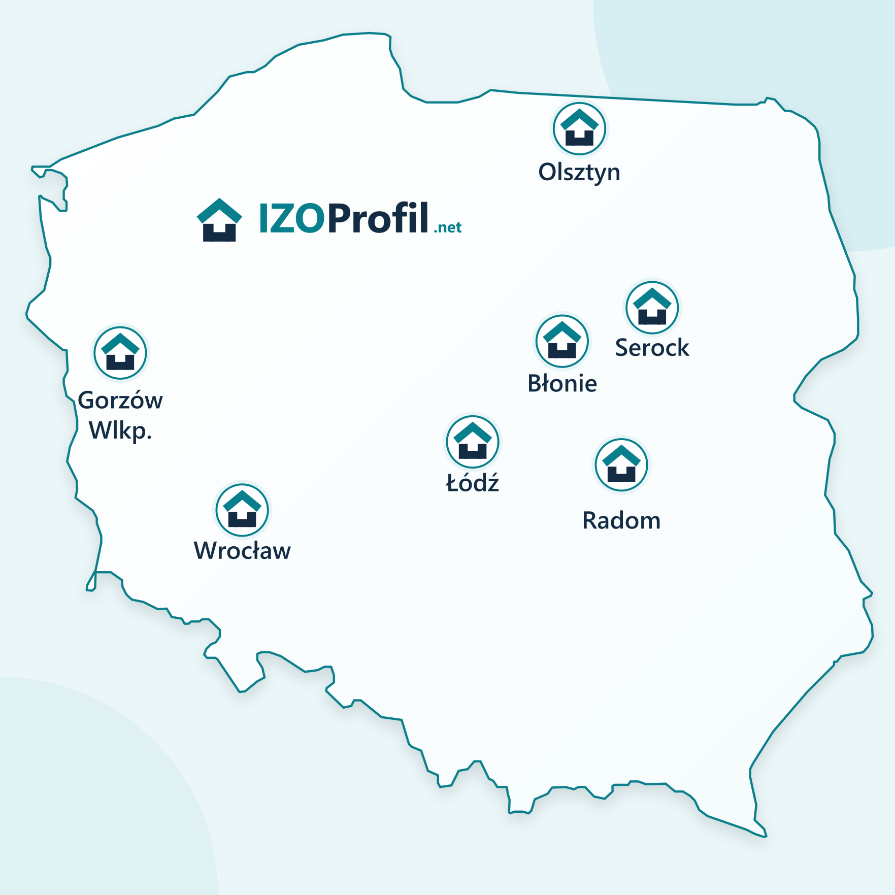
- SEROCK — Dzierżenin 34 E
- BŁONIE — ul. Sochaczewska 138A
- RADOM — ul. Grobickiego 8
- ŁÓDŹ — Natolin 8
- OLSZTYN — Barczewo, ul. Prosta 9
- WROCŁAW — ul. Jerzmanowska 10C
- GORZÓW WLKP. — ul. Zielona 33/34