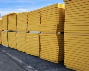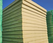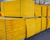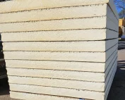


PIR insulation
Installing IDELCO α-therm WALL: checking the wall and joints
At a glance
IDELCO α-therm WALL is used to provide PIR insulation between the layers of a cavity wall. The aluminium laminate is present on both surfaces, but it does not take over the function of the load-bearing wall or the anchors. The crew establishes this division of tasks before distributing the material. The works programme requires acceptance of the condition of the substrate, the board joints and the seating of the anchors before the facing layer is closed. Once the masonry is complete, these places will no longer be easily accessible. The fit of the insulation to the actual openings and the wall geometry must therefore be checked during installation, and not only when the delivery is settled. The contractor must also preserve the function of the cavity and the intended terminations at the window sills, linking the continuity of the thermal insulation with protection against water.
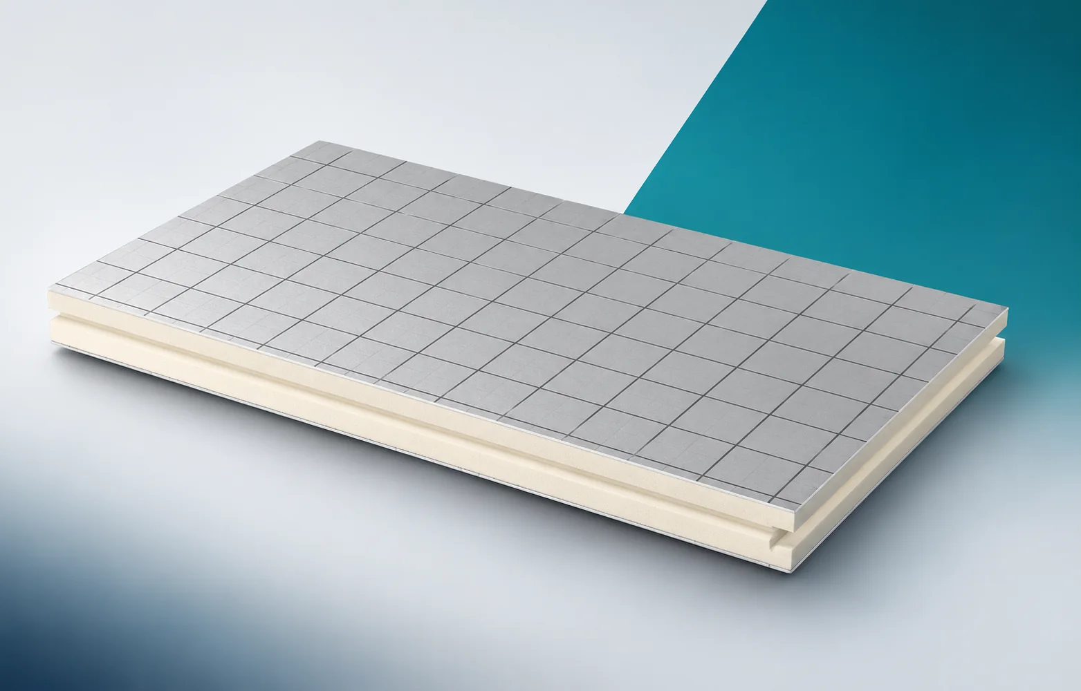
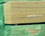
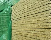
α-therm WALL PIR boards between the wall layers
Delivery of the PIR boards does not conclude the preparations, because a foil-faced board does not take over the structural tasks of the wall. Before separating the material, the team checks the arrangement of the wall, the insulation and the facing layer at the actual openings, so as to make use of the small insulation thickness in a correctly planned cross-section.
Lambda and the geometry of the building component
The thermal conductivity of α-therm WALL is 0.022 W/(m·K). The datasheet range includes various thicknesses, so the choice should not end with the lambda value alone. On the delivery note and the drawing, compare the α-therm WALL 100 mm board with R_D 4.50 m²K/W.
Before using the first batch, the team compares the thermal data of α-therm WALL with the actual geometry of the wall, because anchors, the corner and the lintel do not fit into a single board resistance value. In the record it notes the cross-section of the wall field and the details of the places where the layer ends, so that the installed elements can be linked to the documents.
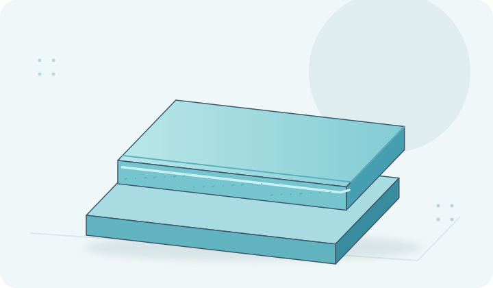
Polyurethane insulation with tongue and groove
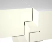
Carry out the tongue-and-groove joint so as not to damage the profile and not to leave open joints. When you cut the edge element to size, you change the factory finish, so resolve the perimeter detail deliberately. At the start of installation, check the tongue-and-groove of α-therm WALL at the last row and at the reveal.
In the starting section, the crew establishes the laying direction of the α-therm WALL 1200 × 600 mm boards and checks that subsequent rows do not repeat the error with the cut edge, because the piece after the cut no longer has the full geometry of the factory joint. Acceptance of the starting section allows the cuts to be adjusted without breaking the tongue and creating accidental gaps. Before the next layer, the laying plan, the condition of the profile and the method of finishing at the perimeter are recorded in the works documentation.
Water at the reveal and under the window sill
The facing layer of the wall and the insulation have different tasks, so plan the drainage of water, the treatment of openings and the protection of the lower part of the building component. When completing the stage, check the drainage of water in the α-therm WALL facing wall.
The gap under the window sill and the termination of the insulation must retain their function until the stage is closed. The aluminium laminate does not replace waterproofing or wall flashings, which is why the crew checks the course of the run-off, the terminations at openings and the possibility of the layers drying out. The polyurethane foam in the board still requires protection; in this way, errors in the continuity of the thermal insulation and in the connection of the water protection are detected before work resumes.
The correct data for the wall variant
The data sheet for this variant states a minimum of 120 kPa at 10% deformation and fire reaction class F. Do not transfer to it the parameters of the ROOF roof board with a similar surface area. Before allowing the next crew onto the completed section, check that α-therm WALL has a CS of at least 120 kPa and reaction F.
The α-therm WALL documents, and not the data for a similar roof board, are the basis for organising the works. A shared brand and facing appearance do not mean identical mechanical properties, so temporary measures also require assessment. At the acceptance of a section, the team confirms the full product designation and the documents for the intended application and clarifies discrepancies before further covering.
Insulation with polyurethane: quantity and inspection before covering
For an α-therm WALL order, prepare a quantity take-off that accounts for openings, the selected board size and the cutting plan. Do not apply the same allowance percentage to every wall: the reserve depends on the actual cutting layout. The assessment of completed work should also include the edge inspection carried out before the outer masonry leaf conceals the insulation.
The quantity take-off for α-therm WALL is linked to the openings and to protecting the material before the wall is closed. A damaged profile makes the joint more difficult at a place that will later be inaccessible for inspection, which is why the schedule of quantities, the cutting plan and the acceptance date for the built-in insulation limit waste and preserve the possibility of inspection before covering. Settlement of the delivery is based on these data and not solely on the number of pallets.
A case worth considering
Make the cut-outs around the anchors so that the board fits as closely as possible. Correct irregularities in the masonry before setting, not by leaving voids behind the board. Before raising the protective layer, accept the corners and the areas around the window sills while corrections are still possible.
7 branches. Materials closer to your project.
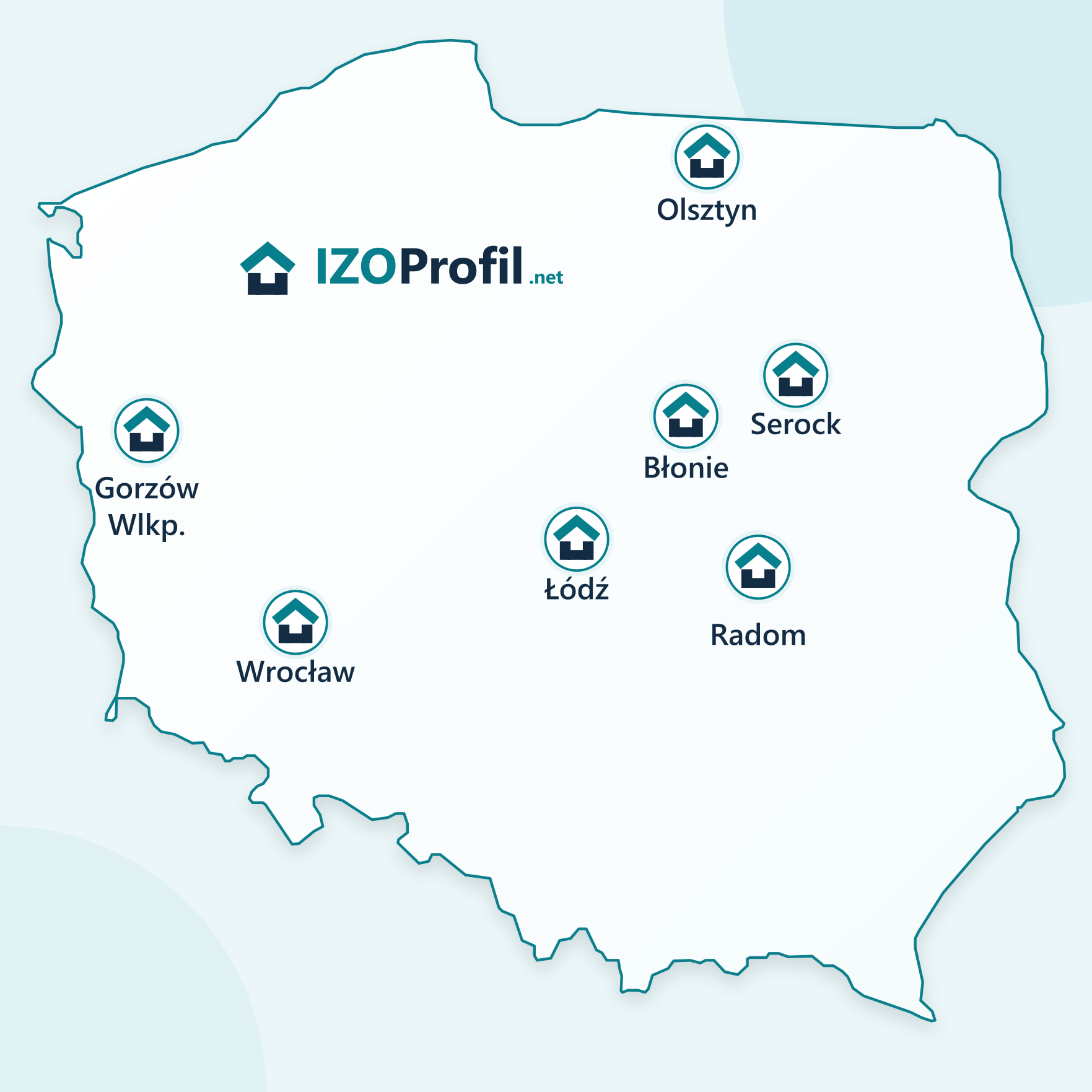
- SEROCK — Dzierżenin 34 E
- BŁONIE — ul. Sochaczewska 138A
- RADOM — ul. Grobickiego 8
- ŁÓDŹ — Natolin 8
- OLSZTYN — Barczewo, ul. Prosta 9
- WROCŁAW — ul. Jerzmanowska 10C
- GORZÓW WLKP. — ul. Zielona 33/34