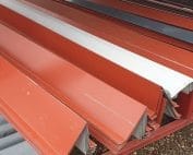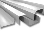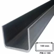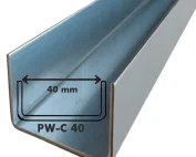
Flashings
Drawing a folded flashing so the workshop can make it as intended
In brief
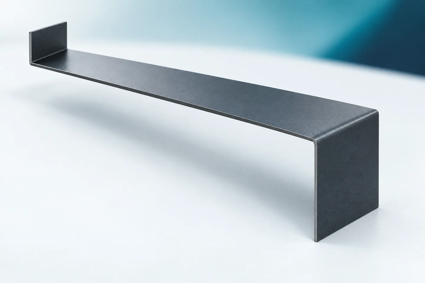
A clear bending drawing can be simple. However, it must show exactly what is to be produced. Unusual flashings require a description of the cross-section, material and length. The side of the coating and the bending directions are also important. An omitted detail can result in a correctly bent component that is unusable in the given location. It is therefore worth preparing the drawing so that the fabricator does not have to infer any dimension. The drawing number should correspond to the item in the schedule. Next to it, write the function name, for example corner cover or eaves strip. Such a name helps identify the application but does not replace the geometry. A single building may contain numerous flashings of similar appearance.
Give the component its own designation
It is worth adding a version or date to the designation. If you change one leg, the previous drawing should be clearly superseded. This avoids producing parts to two different specifications. Verbal corrections should be incorporated before final order confirmation.
Draw the cross-section without perspective foreshortening
The cross-section should show all legs in one plane. It is worth drawing them to scale, but the specified dimensions are what matter most. A photo or spatial sketch can be an addition. It should not be the sole basis for production, as it does not provide reliable lengths and angles.
For complex fabrication, label successive sections with letters. This makes it easier to discuss a specific flange. Ridge caps, verge flashings and starter profiles have different bend configurations. Repeating a general name in the change description is less precise than specifying the dimension of a particular leg.
Define the dimensioning method
It should be established whether the lengths refer to the outer surfaces or to the sections between bend lines. It is worth marking this on the drawing. With thicker material and small flanges, the difference can matter for fit. Bend radii should be agreed with the fabricator.
Every angle must be shown graphically. A notation of 90 or 30 degrees alone, without indicating the location, can be ambiguous. The dimension of the finished cross-section is not always a description of the machine setting. Unusual flashings should therefore be presented as the final shape that is to fit the detail.
Show the coloured side and the installation direction
For coated steel sheet, mark the visible side. A thicker line or an arrow with a short description is helpful. Also indicate where the external side of the building is. An asymmetric profile may look similar when mirrored, but have the coating or drip edge in the wrong position.
Left and right barge flashings require a clear reference. Chimney flashings should be marked with the side relative to the ridge. It is worth showing the gutter aprons with the direction of flow. Such information reduces the risk of turning the finished component during production or installation.

Length, number of pieces and end treatments
The profile length is recorded separately from the cross-section dimensions. The number of pieces must be given for each length. If the ends are cut at an angle, an additional view is needed. Cut-outs, holes and corners must be described in the same way. The cross-section alone does not show them.
Laps and connections must be included in the schedule. The length of the ordered piece does not always correspond to the cover length. Do not order a random allowance from the manufacturer without information about the detail. It is better to specify the required component and separately describe how it connects to the next one.
Material and feasibility
The description should include the thickness, type of steel sheet and surface protection. Galvanised, aluzinc and coated steel sheets are different items. For colour, add the texture and gloss if they are relevant. This information must match the accepted quote and production confirmation.
The manufacturer should check the feasibility of small flanges, tight bends and the required length. Limitations depend on the machine, tooling and material. Not every drawn profile can be produced in any bending sequence. Any correction requires agreement in order to preserve the function of the component.
Walk through the drawing as an installer would
Finally, check how the part will be fitted and fixed. Is there access to the fastener? Will the profile fit into the intended space? Does the bend not close off the drainage? Such questions often reveal a problem that is not visible when looking at the flat cross-section line alone.
For a large batch, it is worth approving a sample. After delivery, compare the markings, number of pieces and basic dimensions with the drawings. Also check the condition of the coating and edges. A well-prepared document remains useful for later ordering of missing or replacement parts.
It is worth keeping the approved drawing together with the material confirmation. When reordering in a few months, the component name alone may be insufficient. An unambiguous version of the document allows the cross-section to be reproduced without re-measuring every flange on the finished building.
Questions and answers
Is a hand-drawn sketch enough to place an order?
It may be sufficient if it is unambiguous and contains all the necessary data. For a complex detail, it is worth supplementing it with views and an agreed shop drawing.
Should the manufacturer calculate the development themselves?
The exact development depends on the bending and the material. The contractor should confirm it technologically on the basis of the agreed cross-section of the finished part.
7 branches. Materials closer to your project.
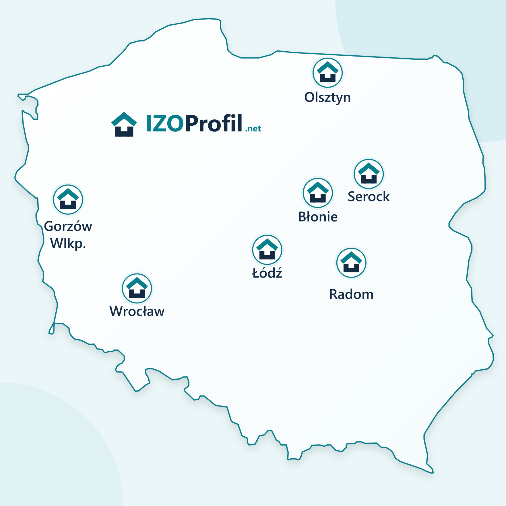
- SEROCK — Dzierżenin 34 E
- BŁONIE — ul. Sochaczewska 138A
- RADOM — ul. Grobickiego 8
- ŁÓDŹ — Natolin 8
- OLSZTYN — Barczewo, ul. Prosta 9
- WROCŁAW — ul. Jerzmanowska 10C
- GORZÓW WLKP. — ul. Zielona 33/34