
Installation and details
Wind resistance on a roof: six points to check during installation
In brief
A roof’s wind resistance depends on the consistent interaction of structure, covering, fasteners and details, not on the number of screws alone. Before measuring, ordering or accepting metal roof tiles, trapezoidal sheeting or sandwich panels, it is worth establishing the loads arising from the building’s location, shape and geometry and from how it is used. The entire path by which forces are transferred should be checked, with particular attention to edges and corners. A fixing pattern should not be copied from another building, because openings, gates and internal pressure affect the working conditions.
1. Match the loads to the building and location
Wind does not act in the same way on every roof. Location, surroundings, building height, its shape and the geometry of the roof slopes all matter. The calculations also take into account the effect of internal pressure within the building. Openings, gates and the way the building is used can affect the working conditions of the envelope. The fixing pattern should therefore not be copied from another building.
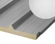
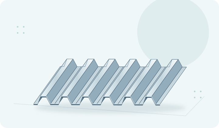
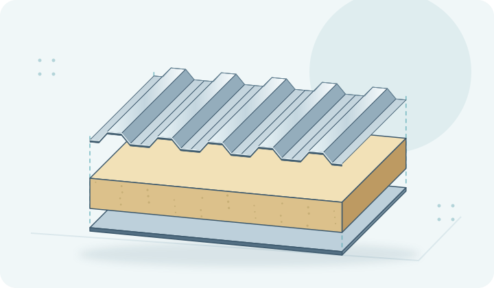
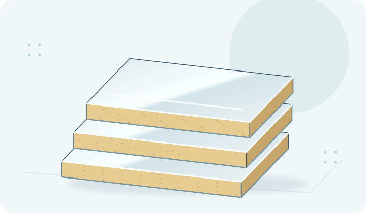
The design should specify the requirements for the covering and its supports. T18, T35 and tile-effect metal roofing have different cross-sections and methods of connection. A sandwich panel is yet another arrangement. The selection must be based on the data for the specific product, the thickness of the facings and the correct structural scheme. The name of a popular profile alone is not a calculation of wind resistance.
2. Check the entire load path
The covering transfers loads to the battens or purlins, and from there to the other structural elements. Every connection along this path must perform in accordance with the design. A strong screw in the sheet will not help if the support is weakened or improperly connected to the structure. During renovation, the old timber, steel and existing fasteners must therefore also be assessed.
The support spacing should not be increased solely to reduce installation costs. Load tables depend on many assumptions, including the number of spans and the direction of loading. Load-bearing capacity and deflection are checked separately. In sandwich panels, restrictions relating to the temperature of the facings and the fire requirements of the entire solution may also matter.
3. Match the fastener to the substrate and load
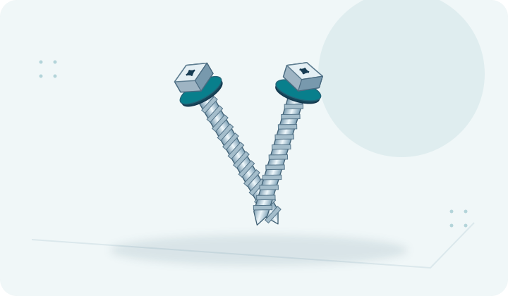
The screw must be selected for timber or steel, the thickness of the parts being joined and the required anchorage depth. The washer, seal and corrosion protection are also important. A similar appearance of two fasteners does not mean they have the same load-bearing capacity. A substitute should be assessed for the specific connection, not used simply because it happened to be left over on site.
Installation must maintain the correct seating position and contact pressure. A skewed screw or a damaged seal can impair tightness, and damage to the substrate can weaken the fixing. For sandwich panels, the rules for the facing and core must be observed. Over-tightening is not a simple way to achieve greater roof resistance.

4. Pay particular attention to edges and corners
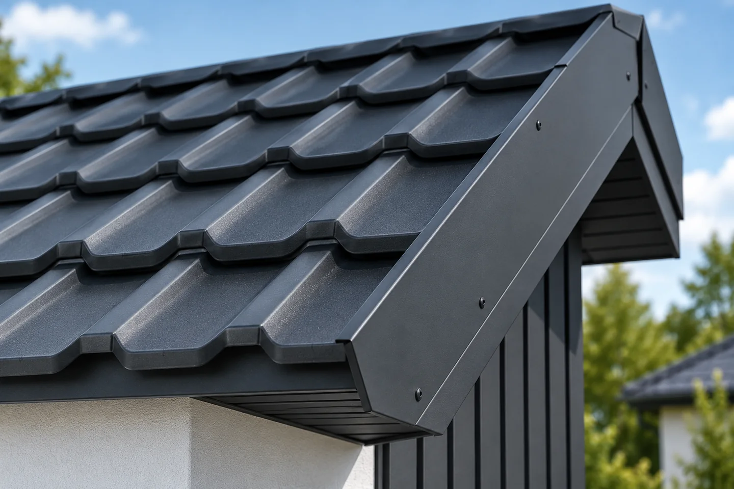
Wind suction may require a different arrangement of fixings in the zones near the roof edge than in the middle part of the roof. The zones and values should be derived from calculations. It is not enough to state an average number of screws per metre over the entire roof slope. What matters is exactly where the fasteners are located and which elements they connect.
Gable, eaves and ridge flashings must be assessed separately. A loose edge can become the starting point of greater damage. The fixing of flashings must suit the material and allow the required thermal movement. Randomly adding screws without understanding the function of the connection can impair tightness or block the movement of the element.
5. Make laps and accessories in accordance with the system
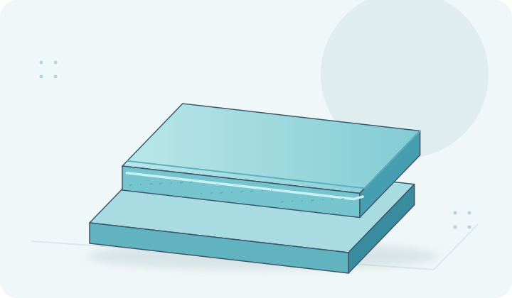
The side overlap, the longitudinal joint between sheets and the fixing to the support each perform different tasks. Each must be carried out in accordance with the product documentation. This applies both to trapezoidal steel sheet and to modules. Sealing does not replace the required mechanical connection. Nor can it be assumed that an additional screw anywhere will improve the entire system.
Chimneys, skylights, equipment and larger openings require planned details. After installing new equipment, the effect of the changes on the covering and the structure must be checked. Elements left loose on the roof can be torn away by the wind. During the works, packs and individual sheets must also be secured in accordance with the safe installation organisation.
6. Check the workmanship and respond to damage
Before covering the layers, it is worth documenting the supports and the way the elements are fixed. Acceptance should cover conformity with the design, the condition of the fasteners, overlaps and flashings. If the contractor has changed the material or the support layout, confirmation of this change is required. The mere fact that the roof looks even does not prove that forces are transferred correctly.
After strong wind, assess from a safe place whether displacements, loose flashings or new leaks have appeared. A thorough inspection requires suitable access and a prepared person. Do not climb onto a damaged roof slope unassisted. The six rules work together: proper design, sound structure, good fasteners, correct zones, details and inspection together form complete protection.
7 branches. Materials closer to your project.

- SEROCK — Dzierżenin 34 E
- BŁONIE — ul. Sochaczewska 138A
- RADOM — ul. Grobickiego 8
- ŁÓDŹ — Natolin 8
- OLSZTYN — Barczewo, ul. Prosta 9
- WROCŁAW — ul. Jerzmanowska 10C
- GORZÓW WLKP. — ul. Zielona 33/34