
Roof structure and design
Choosing timber connectors for a roof frame
In brief
A timber connector is selected for the specific joint, not merely for the beam width. To choose the right connector, you need to check the force directions, the substrate, corrosion protection and the required nails or screws. Even a correctly selected plate will not perform as intended if it is fastened randomly. It is therefore worth starting with the joint drawing and information on the forces transmitted, then analysing the technical documentation. This will help prepare an order for timber roof truss connectors that comply with the design and installation conditions.
What task is the connector to perform?
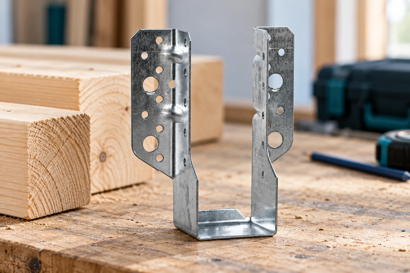
Start with the joint drawing and information on the forces to be transferred. A beam hanger, angle bracket and rafter-to-purlin connector are not interchangeable. Each element has a specific application. It is also important whether it connects timber to timber, or to concrete or steel. The same external appearance does not mean the same fixing rules for different substrates.
The connection may be loaded downwards, upwards or horizontally. The roof must remain stable also under wind suction. It is therefore not enough to check only the load from weight. In the connector documentation, the directions are usually described by drawings and tables. Their designations must be related to the actual position of the element on site.
How to read the load-bearing table
Check for which material, fastener arrangement and conditions the values are given. The table may contain characteristic load-bearing capacities or values requiring further structural design calculations. Not every number should be treated as a ready permissible service load. The timber class, the duration of load action and the relevant coefficients may be significant.
Pay attention to footnotes and installation drawings. Sometimes a parameter applies to a pair of connectors, a specific angle or a specific number of nails. Taking a single value from the table removes these conditions. If the design provides for a different arrangement, its admissibility must be checked. It is not enough to select the next, seemingly stronger model without checking the entire connection.
Why the right nails and screws are part of the system
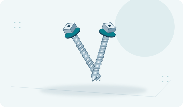
The diameter, length, shape and material of the fastener affect the performance of the connector. The documentation specifies the products approved for a given solution. An ordinary screw for fixing cladding may have completely different properties from a structural screw. It should not be used as a substitute simply because it passes through a hole in the steel plate.
Some systems permit the replacement of specific nails with specific screws. This must, however, follow from the relevant table or instruction. Partial nailing also has a defined hole arrangement. It does not mean an arbitrary reduction in the number of fixings. The purchase list should therefore specify not only the connectors but also the fasteners that match them.

How to choose dimensions and corrosion protection
The connector must match the timber cross-section and ensure the required fixing distances. The width, height, length of the arms and the position of the holes are important. An element that is too small may hinder the correct arrangement of the fasteners. An element that is too large cannot always be correctly supported or installed. The fit is checked on the drawing of the entire joint.
The type of steel protection should match the service environment. A dry interior and an exposed terrace canopy are different conditions. The type of wood preservative used and material compatibility must also be taken into account. Not every galvanised component is suitable for every location. The choice of protection follows from the product documentation and the anticipated exposure.
What errors occur during installation?
A common problem is incomplete pressing of the connector against the timber, installation in the wrong direction, or omission of the component on the other side. Damage to the timber also occurs where distances from the end are too small. Holes must not be enlarged at will, arms cut, or the profile straightened in a way not provided for in the documentation. This changes how the product performs.
Check the installation sequence before the components close off access to the holes. In some locations the connector must be fixed in advance. Lack of access is not solved by omitting a few nails. If the actual structure differs from the drawing, the correct variant must be established. A repair carried out before the roof structure is covered is often far simpler than subsequently dismantling layers.
What should be included in the purchase and acceptance documentation?
Record the exact designation of the connector, the number of pieces, the type of fixings and the place of use. Keep the technical documentation and the relevant declarations. Product marking does not mean that it is suitable for any connection. It confirms specific properties that must be correctly applied in the design and during installation.
At acceptance, compare the workmanship with the schedule before the structure disappears under the insulation. Check the types of connectors, their number and the condition of the timber at the joints. It is worth taking photographs of representative and difficult details. A good connector is part of a complete solution: the right beam, the correct substrate and precisely executed fixing.
7 branches. Materials closer to your project.
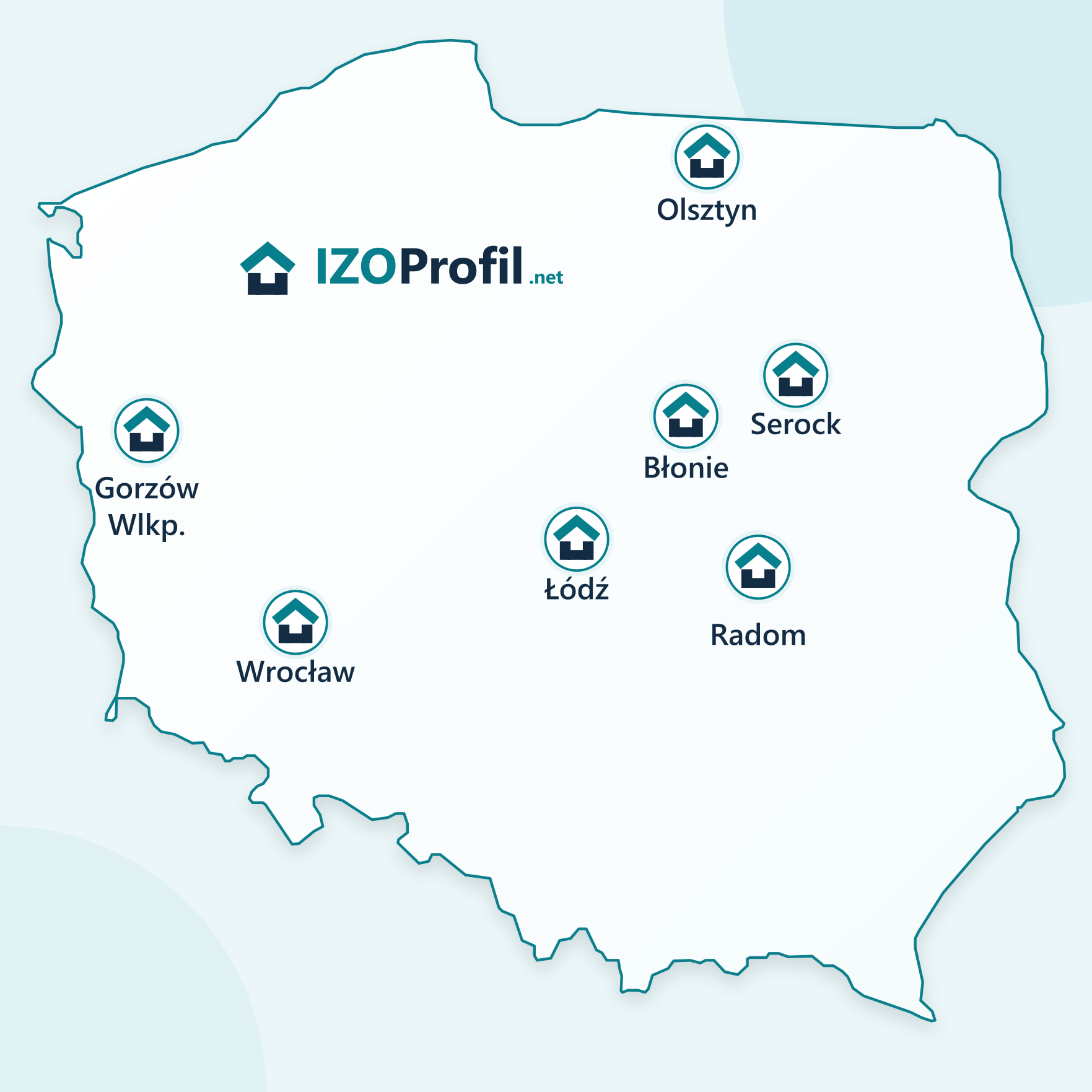
- SEROCK — Dzierżenin 34 E
- BŁONIE — ul. Sochaczewska 138A
- RADOM — ul. Grobickiego 8
- ŁÓDŹ — Natolin 8
- OLSZTYN — Barczewo, ul. Prosta 9
- WROCŁAW — ul. Jerzmanowska 10C
- GORZÓW WLKP. — ul. Zielona 33/34