

PIR insulation
IKO enertherm ALU TG: joining boards without damaging the edges
At a glance
The key point with IKO enertherm ALU TG is that once the board is cut, it loses the factory profile on one edge, so further joining depends on how the cutting plan was drawn up. Before the team starts laying the rows, it should have a plan with the cut edges marked, as well as the measured width of the last strip and the position of the joint ends. It is also worth establishing the unloading point and the sequence of work. Offcuts are set aside according to their intended use, because accidentally turning a piece round makes later joining more difficult. The cutting plan and laying direction are determined before the last strip is prepared in series, so that any discrepancy does not increase waste.
Preparing the working section
The common aim of the works is to make the joints between full boards and cut pieces without gaps in the layer. As regards the detail solution, the necessary arrangements are communicated by the coordinator for cutting and laying ALU TG.
The actual product and the scope of its data
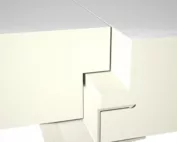
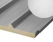
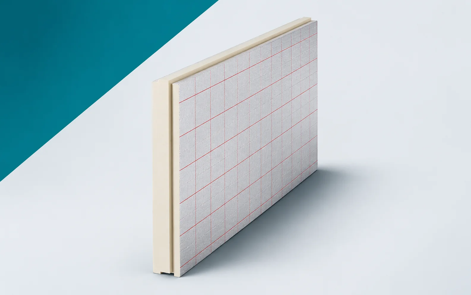
In IKO enertherm ALU TG the core is made of PIR and the facing is an aluminium laminate; the edge has a tongue-and-groove profile. For the family, a lambda of 0.022 W/(m·K) and a compressive stress of at least 175 kPa are given. The reaction to fire is F, whereas B-s2,d0 refers to a specific end use. The TG profile does not act as a structural connection or as standalone waterproofing, and after cutting the edge loses its factory shape. During installation, what matters is therefore making the joints between full boards and cut pieces without gaps in the layer, taking into account the properties of the whole board, not just the core.
A calculation to help with planning
Example: an ALU TG layer with an area of 42 m² and a thickness of 100 mm corresponds to 4.20 m³ built into an ideally full field. This is a geometric volume, not a transport volume — packs and allowance may require a different one. Nor does this calculation give the permissible load on the structure at the storage location. During laying, a level substrate is needed, without forcing the position of the joint by force, as well as access to the edge of the cut piece that is free of the factory tongue. The volume serves for planning space and does not replace the principles of safe support of the material.
The value from the example for IKO enertherm ALU TG refers to a specific section of the works, not to the entire delivery. The site condition is the absence of the factory profile on the edges after cutting — the places where it is lost must be indicated on the drawing before repeated laying. The working document is the row plan with the edges remaining after cutting marked. The tongue-and-groove profile in the ALU TG variant itself helps to identify the variant, but does not replace measurement of the completed area. Material separated from full packs also requires clear marking.
Decision before replicating the layout
The first ALU TG run sets the rhythm for the rest of the work, so before it is laid a decision is made whether the project provides for changing the width of the first row for a more favourable final cut, or for keeping the full first row with a separate perimeter solution in line with the agreed change. The trial covers the cut edge without a preserved factory tongue, not only the easy unobstructed field; not every cut piece is an element with a complete factory joint. The result is assessed by the coordinator of the ALU TG cutting plan and laying before the team moves on to a larger scope. After the change, the cutting plan with the laying direction and termination details is updated so that the delivery and the cutting station work to the same data.
What to check during fitting
During the laying of ALU TG, the geometry of the joint is determined by the tongue-and-groove profile with intact and matching edges, and the aluminium laminate of the ALU TG variant must be handled without damaging the surface. The layers are laid on a levelled substrate, without forcing the position of the joint by force. At acceptance, a description of the fit of the tongue in the groove and of the perimeter sealing is produced, drawn up on site. Finishing follows acceptance of the joints, so any misfit is corrected beforehand. The cut edge without a preserved factory tongue is checked separately, since continuity is easily lost there during cutting or a change of working direction.
Delivery matched to the team’s capacity
The delivery of ALU TG to the station corresponds to the scope that can be prepared and secured. The cutting plan with the laying direction and termination details organises the layout of the material, and access to the cut edge without a preserved factory tongue remains clear so that acceptance does not require moving the entire delivery. The plan for the work break takes into account the finishing laid after acceptance of the joints and the protection of the open boundary. After a change of front, the absence of the factory profile on the edges after cutting is reconsidered. The boards remain identifiable by variant, not by where the pack was set down.
Handover of the completed layer
The handover of the thermal insulation joined with a factory tongue and groove is based on comparing the state of the works with the drawing and the agreed corrections. For IKO enertherm ALU TG, identification is provided by the description of the fit of the tongue in the groove and of the perimeter sealing. It is recorded whether the completed scope allows full boards and cut pieces to be joined without gaps in the layer. The next team receives a row plan marking the edges remaining after cutting and the places requiring care. The records cover the execution of the cut edge without a preserved factory tongue and the person approving this section, so that the insulation is handed over as a checked part of the works, not as an occupied area of the site.
7 branches. Materials closer to your project.
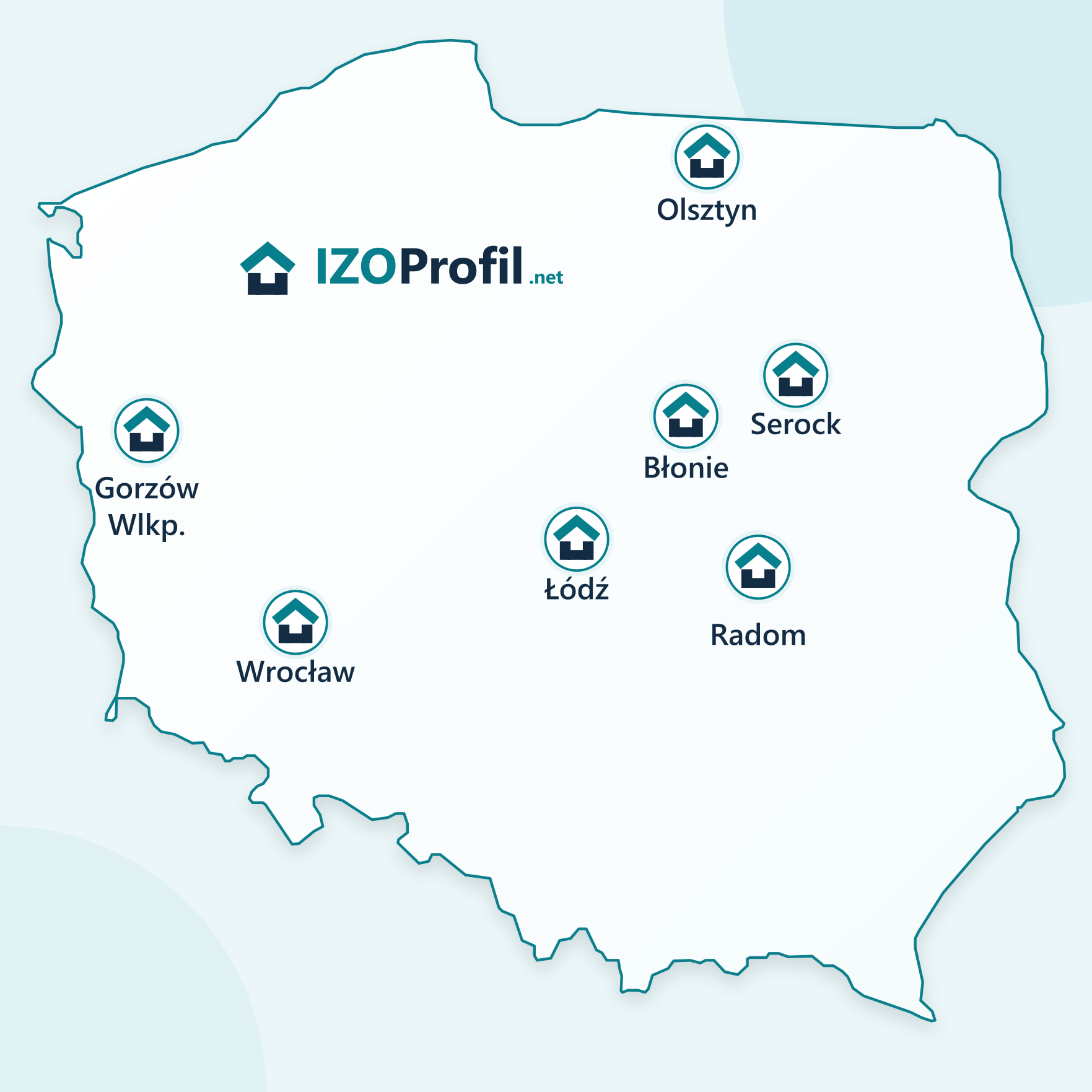
- SEROCK — Dzierżenin 34 E
- BŁONIE — ul. Sochaczewska 138A
- RADOM — ul. Grobickiego 8
- ŁÓDŹ — Natolin 8
- OLSZTYN — Barczewo, ul. Prosta 9
- WROCŁAW — ul. Jerzmanowska 10C
- GORZÓW WLKP. — ul. Zielona 33/34