


Steel halls and structures
Foundations and anchor bolts: setting out a steel building accurately
In brief
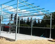
The frame arrives with pre-drilled holes, and the anchor bolts are already waiting in the concrete. These two scopes must meet in a precisely defined geometry. That is why the starting point of a steel hall requires good data exchange between designers and contractors. Later forcing the base plates to fit is not a way to resolve discrepancies. The check should take place earlier, before the first columns are positioned over the foundations. Foundations are designed taking into account the ground, water and the loads of the steel hall. The steel structure transfers vertical, horizontal and other actions resulting from the adopted layout. Knowing the hall area alone is not enough. Two similar buildings may require different solutions due to location, equipment or geotechnical conditions.
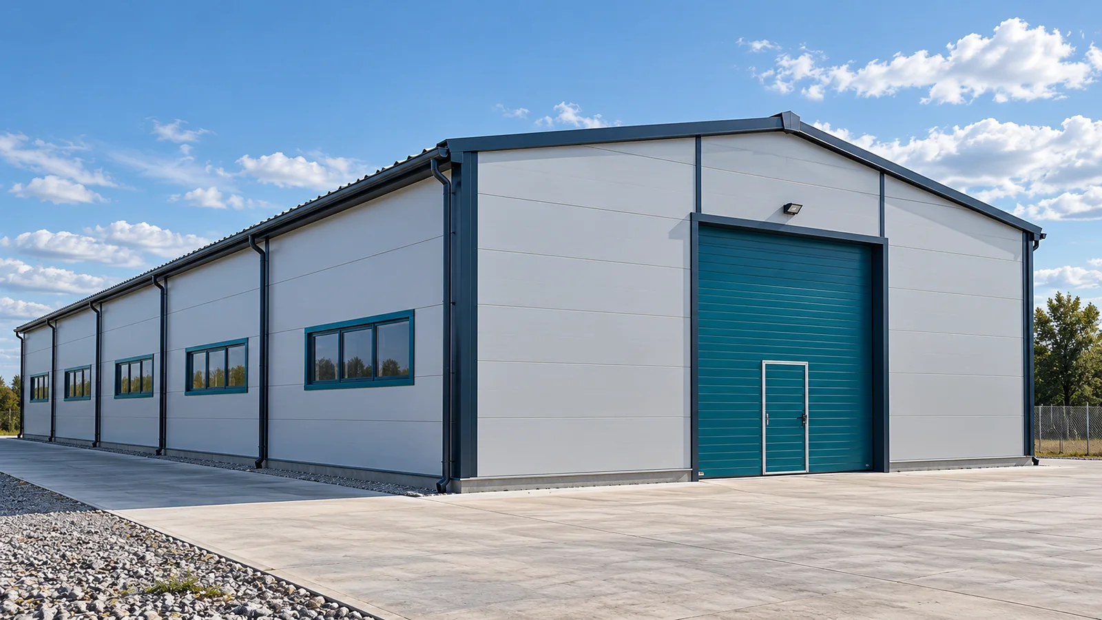
The ground determines the foundation conditions
In a steel hall, the foot dimensions from another project should not be copied without assessment. The foundation levels and the proximity of existing elements are also important. If services run nearby or excavations are planned, they must be taken into account. The foundation is part of a specific project, not a repeatable addition to any set of frames.
Data exchange must be unambiguous
The foundation designer needs information on the reactions and the design of the column bases. The anchor installer must know their position, dimensions and installation requirements. The steel structure should be described in the same version of the documentation. A shift of the axes or a change of column type must reach all scopes before work is carried out.
Establish who issues the data and who approves it. A steel hall must not be erected on a foundation designed to outdated assumptions. Attention should be paid to the measurement reference system. Axial dimensions, external dimensions and finished floor levels describe different things. Confusing them can cause discrepancies even when the numbers themselves are read correctly.
Anchor bolts are checked before and after concreting
Setting out the anchors requires checking position, spacing and levels in accordance with the documentation. It is important to maintain this geometry during the works. Once completed, measurements are needed to assess readiness for erection. In a steel hall, merely stating that the anchor cage does not look displaced does not provide sufficient information.
The results should be compared with the requirements and tolerances specified for the project. Any non-conformities must be reported before the elements are set. Steel structures should not be adjusted by randomly bending anchors or enlarging holes. The method of repair requires an assessment of its effect on the connection and approval of the appropriate solution.

The column base acts as a connection
The base plate, anchors, support and any grouting form a specific detail. Its execution must correspond to the design assumptions. The nuts must not be regarded as the only element ensuring correct behaviour of the base. The steel structure transfers forces through the entire intended system, not through the visible fragment of the anchor alone.
The sequence of operations and the required condition of the materials should follow from the documentation and the erection plan. A steel hall may require temporary protection during construction. Load transfer should not be accelerated without confirmation of readiness. The appearance of the concrete or mortar surface does not replace verification of the conditions that must be met.
The floor does not replace the foundations
The hall floor has different tasks from the column foundations, although the solutions may be interrelated. The floor slab is selected according to use, loads and traffic. The foundations take the loads of the frame. A steel hall should not rest on a randomly executed slab merely because the concrete appears thick and level.
Insulation, expansion joints and services routed beneath the floor require coordination. Footings may occupy space needed for equipment or racking. It is better to resolve these dependencies on the plan than during later drilling. Steel structures and equipment must be provided with adequate support without damaging other parts of the building.
Keep a record of the inspection
Prepare the measurement results, the works documents and information on approved changes. These facilitate the assessment of readiness and the subsequent use of the building. If a deviation has been identified, the record should indicate how it was resolved. The absence of a description makes it difficult to determine whether an element was executed in accordance with the design or merely adjusted on site.
Before delivery of the steel hall, it is worth checking the interface between the scopes of work together. The surveyor, the foundation contractor and the steel erection crew need the same data. An accurate start reduces the risk of equipment downtime and rework. The steel structure can then be placed on the prepared bases in the order resulting from the plan, without seeking ad hoc ways to remove geometry errors.
When handing over measurement results, use the same axis designations as on the erection drawings. A description referring to the left corner is ambiguous if the participants are looking from different sides. The axis number and reference level also allow the location requiring inspection to be indicated precisely.
7 branches. Materials closer to your project.

- SEROCK — Dzierżenin 34 E
- BŁONIE — ul. Sochaczewska 138A
- RADOM — ul. Grobickiego 8
- ŁÓDŹ — Natolin 8
- OLSZTYN — Barczewo, ul. Prosta 9
- WROCŁAW — ul. Jerzmanowska 10C
- GORZÓW WLKP. — ul. Zielona 33/34